Part number: 64-0161-02
Dialogic
®
DISI16-EW,
DISI24-EW, and
DISI32-EW
Installation Guide
Copyright © 2006-2007 Dialogic Corporation.
All rights reserved.
1. Product Description
The Dialogic
®
DISI switching boards are full-size,
single-slot PCI Express boards. They provide
connectivity for up to 16, 24, or 32 station interfaces
and include conferencing, voice play/record, tone
detection and generation, and Caller ID capabilities.
Additional Information
Additional information about the DISI is available
from a number of sources.
The product data sheet, available at http://
www.dialogic.com/products/list.asp, provides a
functional description as well as information about
applications and configurations, features, and
technical specifications.
Refer to the Release Guide and the online Release
Update for your Dialogic system software release to
verify that the DISI is supported in the release and
for information on any new features or issues that
may relate to it.
The Regulatory Notices document that is packed with
each DISI board contains safety warnings and
national requirements for proper operation of
telecommunications equipment.
WARNING! This analog station interface
product is designed to be used only within the
walls of a single stand-alone building or
structure (i.e., on-premise). It is not designed
to sustain electrical overstress from external
sources and factors such as severe weather
conditions. Severe electrical overstress caused
by misuse of this interface product with cables
extending outside of the walls of a single stand-
alone building or structure could cause property
damage and/or personal injury and/or death.
Such misuse voids the warranty for this
interface product.
2. Before You Begin
Protecting the Board from Damage
CAUTION: All computer boards are sensitive to
electrostatic discharge. Handle all static-sensitive
boards and components at a static-safe work area,
and observe anti-static precautions at all times.
If you are not familiar with ESD safety precautions,
visit http://www.dialogic.com/support/hwinstall to
learn more.
Unpacking the Board
Unpack the board according to the following steps:
1. Prepare a static-safeguarded work area.
2. Carefully remove the board from the shipping
carton and static-shielding bag. Handle the board
by the edges and avoid touching the board's
components.
3. Lay the board on the static-dissipative work
surface.
Note: Place boards in static-shielding bags when
carrying boards from station to station.
CAUTION: Do not remove the board from the anti-
static packaging until you are ready to install it.
Observe proper anti-static precautions at all times.
3. Configuring the Board
Setting the Board ID
When the system is started, each Dialogic telecom
board is assigned a board instance ID number that
programs can use to identify individual boards in a
multi-board system. The setting of SW100 controls
the generation of the instance numbers.
Windows* Systems: In a Windows system, leave
SW100 set to the 0 position (the factory default
setting) on all Dialogic telecom boards. This setting
causes the system software to assign instance
numbers geographically, based on the bus and slot
numbers. Note that there is no way to know what
the instance numbers will be until the system is
started and configured, and the instance number
for any given board is likely to change when there
is any change in the number or arrangement of
boards in the system.
You can read the ID numbers assigned to the
boards in the Configuration Manager tool after you
start the system.
Linux* Systems: In a Linux system, you must
explicitly specify the board ID numbers by setting
SW100 on each board to a different position (0-9
or A-F). Refer to the Configuration Guide in your
System Software documentation for further
information about the board ID numbers.
4. Choosing a Slot
The DISI board is a full length x1 form factor PCI
Express board that requires 25W of power. The
following explanation and guidelines are provided to
ensure proper configuration of the product.
Power Budgeting is a new feature, introduced in the
PCI Express Specification, that provides a mechanism
to enable a system to negotiate power consumption
requirements for add-in devices.
Per PCI Express Card Electromechanical Specification
Revision 1.0a or higher, a x1 add-in card can draw no
more than 10W in a x1 slot unless the board’s
required power is successfully negotiated and
allocated by the system (power budgeting). However,
implementation of power budgeting by a vendor's
system is not a compliance requirement per the PCI
Express Card Electromechanical Specification
Revision 1.0a or higher. Therefore, some chassis may
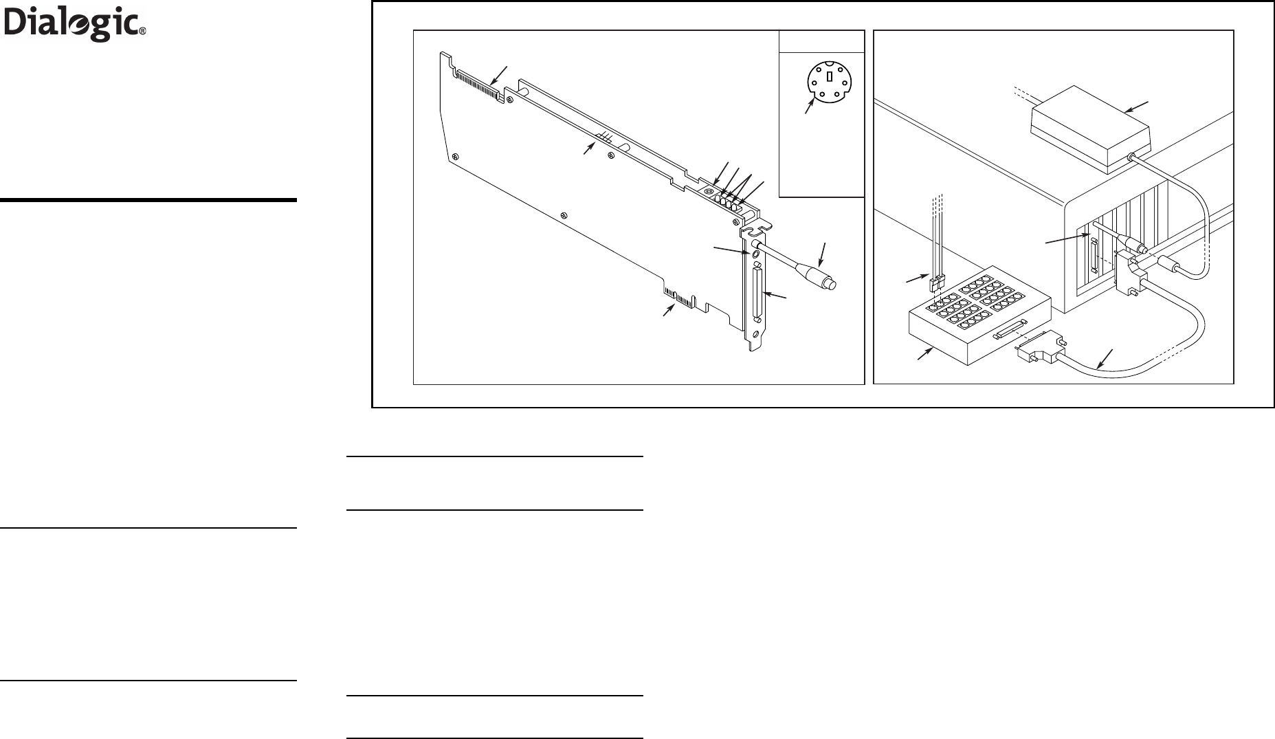
Physical Layout
Connect Breakout Box and Power Supply
Power
Supply
DISI
Board
Breakout
Cable
To
Telephone
Extensions
Breakout
Box
RJ-11
Cables
Physical Description
12
65
34
Pinouts for the
Power Connector
1
2
3
4
5
6
-24/-70 Return
PC Sens
-24 Volts
-24/-70 Return
-24 Volts
-70 Volts
Chassis
Ground
CT Bus (H.100) connector
SW100 - Rotary switch used to set board
identification number
Green LED - Power On indicator
Yellow LEDs - User-defined #1 and #2
Red LED - Out of Service indicator
1.
2.
3.
4.
5.
Power Budgeting Jumper P4 - 3-pin jumper
to set how the board responds to the
system power budgeting function
-P4 jumper in pins 2-3: Board adheres to
power budgeting values set by system.
-P4 jumper in pins 1-2: Board ignores
power budgeting values set by system.
Factory default is P4 jumper in pins 2-3.
Power supply connector - Connects to
external power supply
Breakout connector - Connects to telephone
breakout box
PCI Express connector - for x1 or larger PCI
Express Link connectors
Audio Input Jack - for music on hold feature
6.
7.
8.
9.
10.
1
2
3
4
9
10 11
12
25
26
27
28
17 18
19
20
5
6
7
8
13 14
15
16
29
30
31
32
21
22
23 24
To AC
Power
10
1
4
7
8
9
2
3
5
123
6


