CAUTION: If your BIOS is set to use Plug and Play
technology and there are ISA boards in your system,
an IRQ conflict can be created if the DM3 board is
assigned the same IRQ as an ISA board. This could
cause the machine to stop responding. You can prevent
this by entering the BIOS and reserving the appropriate
IRQs (those used by your ISA boards) for ISA use
only.
10. Replace the chassis cover when finished and reconnect
the power cords.
NOTE: Your system may include both CT Bus and
SCbus boards. To connect both board types, you must
install a CT Bus/SCbus Adapter on one of the CT Bus
boards in a system. See the CT Bus/SCbus Adapter
Quick Install Card for installation details about the
Adapter and the bus cables. Contact your Dialogic
Sales Representative to order an Adapter.
9. Install CT Bus Termination Jumpers only on boards
located at each end of the CT Bus cable. See Physical
Description section.
8. Use the CT Bus cable to connect the board(s) you are
installing to other boards in the system.
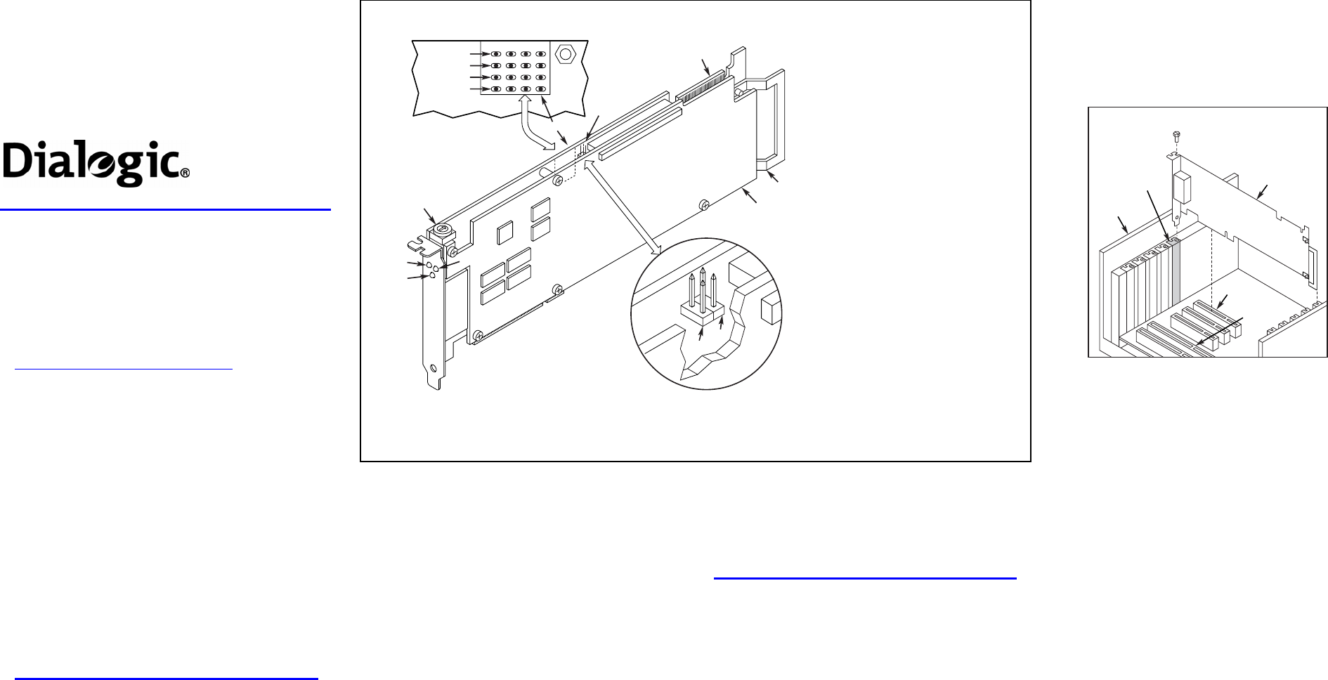
6. Replace and tighten the slot’s retaining screw to
secure the board firmly in the chassis (if applicable).
5. Using the slot’s board guides, insert the board edge
connector into the bus slot. Press firmly until the
board is securely seated in the slot.
4. If you are not installing your board in an ISA form
factor PCI slot, remove the ISA edge retainer from
the board.
7. Select a new PCI slot and repeat steps 3-6 for each
board you are installing.
Installing a PCI Board
16-Bit
ISA Slot
32-Bit
PCI Slot
PCI
Board
Computer
Chassis
Remove
Cover
Plate
11. Turn the power to the chassis ON.
Dialogic
®
DM3 Media Boards
Quick Install Card for PCI
DM/V2400A-PCI
Part Number 64-0017-02
Copyright © 2001-2007
Dialogic Corporation.
All Rights Reserved.
Before You Begin
Protecting the Board from Damage
CAUTION:
All computer boards are sensitive to
electrostatic discharge (“ESD”). Handle all static-sensitive
boards and components at a static-safe work area,
and observe anti-static precautions at all times.
If you are not familiar with ESD safety precautions, visit
http://www.dialogic.com/support/hwinstall to learn more.
Unpacking the Board
Unpack the Dialogic
®
DM3 Media Board (“board”)
according to the following steps:
1. Prepare a static-safeguarded work area.
2. Carefully remove the board from the shipping
carton and anti-static packaging. Handle the
board by the edges and avoid touching the
board’s components.
3. Lay the board on the static-dissipative work
surface.
NOTE: Place boards in static-shielding bags when
carrying boards from station to station.
CAUTION: Do not remove the board from the anti-static
packaging until you are ready to install it. Observe proper
anti-static precautions at all times.
Configuring the Hardware
Board Identification
The Dialogic
®
DM3 device driver, part of the Dialogic
®
System Software, assigns board instance numbers in
ascending order (beginning with 0) as it detects each board
in your system. A board instance number is the
identification (ID) number used by the system software to
recognize the board.
NOTE: If you add a board to the system, the existing
board instance (ID) numbers may change, depending upon
the PCI bus and slot number where the new board is
installed.
Windows System
After the Dialogic
®
hardware and the Dialogic
®
System
Software are installed, refer to the Dialogic
®
Configuration
Manager (DCM) utility to retrieve the board instance (ID)
number(s) assigned to the board(s) in your system.
See the DCM online help for more details about board
identification.
Linux System
In a Linux system, you must set SW1 to a unique number
for each installed board in your system. Use a non-
magnetic screwdriver to turn SW1 to 1 of 16 board
settings, 0-9 or A-F.
After the Dialogic hardware and Dialogic System Software
are installed, refer to the proper configuration files to
retrieve the assigned board instance (ID) number(s)
assigned to the board(s) in your system. For more
information about Linux configuration files, see the
Dialogic® Software Installation Reference.
Installing the Hardware
NOTE: Dialogic recommends that you install Dialogic
®
hardware before Dialogic
®
software. However, if you are
adding hardware to an existing system, you do not need to
uninstall existing Dialogic software.
1. With your computer on the static-safe work area,
switch off the power and disconnect all power cords
from the electrical outlets.
2. Remove the chassis cover plate.
3. Select an empty PCI expansion bus slot and remove
the slot’s retaining screw and access cover plate (if
applicable).
Physical Description
4
9
8
7
1
2
3
JP2B
JP2A
6
5
Red
Yellow
Green
Loopback
CH4CH3CH2CH1
1. General Network Interface Alarm
LED (not applicable)
2. Power LED
3. Reset LED
4. SW1: Rotary switch to set board
identification (UNIX systems only).
5. POST LEDs: Indicate Power On Self
Test (POST) status during power up.
Alarm Status LEDs:
Red-Not functional in this
assembly.
Yellow- Not functional in this
assembly.
Carrier Signal- Not functional
in this assembly.
Loopback- Not functional in
this assembly
6. CT/MVIP Bus Termination
Jumpers: Bus signal is terminated
when the corresponding jumper is
installed. Signal must be terminated
only on boards at each end of the
CT Bus cable.
JP2A: CT Bus termination jumper
JP2B: MVIP Bus termination jumper
8. ISA Edge Retainer
9. Signal Processing Daughterboard
7. P3: CT Bus connector


