


Part number: 64-0278-01
Dialogic
®
DNI2410TEPEHMPQ
Board
Installation Guide
Copyright © 2007 Dialogic Corporation. All rights reserved.
1. Product Description
The Dialogic
®
DNI2410TEPEHMPQ board
(“DNI2410TEPEHMPQ” or “board”) is a high-density,
high-performance, network interface board with eight
T1/E1 digital network interfaces in a full-length PCI
Express form factor.
The DNI2410TEPEHMPQ includes the following com-
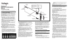
ponents, shown in the Physical Layout illustration:
RJ-48C jacks: Four connectors, each of which con-
nects to two T1 or E1 trunks via a splitter cable.
Refer to the Physical Layout illustration for the
trunks supported by each connector. The splitter
cable set (four splitter cables) is provided with the
board.
General Network Interface Alarm LED: When lit
(yellow), indicates that an alarm condition is
present on one or more of the trunks. When unlit,
alarm conditions are cleared.
Reset LED: When lit (red), indicates that the board
is in the reset state. When unlit, the board is no
longer in the reset state.
Power LED: When lit (green), indicates that board
power is good. When unlit, either power has not
been applied to the board, or the board has de-
tected that one or more of the on-board-generated
voltages are not correct.
SW1: Rotary switch used when setting board ID.
Alarm/status LEDs: A set of four LEDs for each
trunk. Refer to the Physical Layout illustration for
LED arrangement.
During power-up, the LEDs indicate Power-On Self
Test (POST) status. After the board is started, the
green, yellow, and red LEDs indicate normal opera-
tion or Carrier Failure Alarms (CFAs) for each trunk,
as shown in the following table. The Loopback LED
indicates when the respective trunk is in loopback
mode.
Green Yellow Red Indicated Condition
ON OFF OFF Normal operation
OFF OFF ON Loss of Signal (LOS)
ON OFF ON Red Alarm
ON ON OFF Yellow Alarm/Remote Alarm
Indicator (RAI)
ON ON ON Alarm Indicator Signal (AIS)
Power Budgeting Jumper P10: 3-pin jumper to
set how the board responds to the system power
budgeting function.
■
P10 jumper in pins 2-3: Board adheres to power
budgeting values set by system.
■
P10 jumper in pins 1-2: Board ignores power
budgeting values set by system.
Factory default is P10 jumper in pins 2-3.
CT Bus Connector: H.100 computer telephony bus
connector.
P5: CT Bus termination jumper block. Only the
boards in the end positions of a CT Bus cable
should be terminated. Factory default is untermi-
nated (clip installed over one pin only).
PCI Express connector: Host bus connector. Com-
patible with x1 or larger PCI Express Link connec-
tors.
Additional Information
Additional information about the DNI2410TEPEHMPQ
is available from a number of sources, such as via its
product data sheet, which is accessible at http://
www.dialogic.com/products/list.asp
. The product data
sheet provides a functional description of the
DNI2410TEPEHMPQ, as well as information about its
applications, configurations, features, and technical
specifications. Please note that Dialogic may make
changes to specifications, product descriptions, and
plans at any time, without notice.
Refer to the Release Guide and the online Release
Update for your Dialogic software release to verify
that the DNI2410TEPEHMPQ is supported in the re-
lease, and for information on any new features or is-
sues that may relate to it.
The Regulatory Notices document that is packed with
each DNI2410TEPEHMPQ contains safety warnings
and national requirements for proper operation of
telecommunications equipment. Please read the doc-
ument carefully before any handling, installation,
connection or other usage or implementation of the
board.
2. Before You Begin
Protecting the Board from Damage
CAUTION: All computer boards are sensitive to elec-
trostatic discharge. Handle all static-sensitive boards
and components at a static-safe work area, and ob-
serve anti-static precautions at all times.
If you are not familiar with ESD safety precautions,
visit http://www.dialogic.com/support/hwinstall
to
learn more.
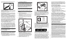
Unpacking the Board
Unpack the board according to the following steps:
1. Prepare a static-safeguarded work area.
2. Carefully remove the board from the shipping car-
ton and anti-static packaging. Handle the board
by the edges and avoid touching the board's com-
ponents.
3. Lay the board on the static-dissipative work sur-
face.
Note: Place board in static-shielding bag when carry-
ing board from station to station.
CAUTION: Do not remove the board from the anti-
static packaging until you are ready to install it. Ob-
serve proper anti-static precautions at all times.
3. Configuring the Board
The DNI2410TEPEHMPQ uses Plug and Play technol-
ogy to simplify installation. No user configuration is
required for IRQ or memory address.
The DNI2410TEPEHMPQ has the following manually
configurable options:
■
Board ID
■
CT Bus termination
■
Power budgeting (see Choosing a Slot section be-
low)
Setting the Board ID
When the system is started, each Dialogic
®
board is
assigned a board instance ID number that programs
can use to identify individual boards in a multi-board
system. The setting of SW1 controls the generation of
the instance numbers.
Windows* Systems: In a Windows system, leave
SW1 set to the “0” position (the factory default set-
ting) on all Dialogic boards. This setting causes the
system software to assign instance numbers geo-
graphically, based on the bus and slot numbers.
Note that there is no way to know what the in-
stance numbers will be until the system is started
and configured, and the instance number for any
given board is likely to change when there is any
change in the number or arrangement of boards in
the system.
After the hardware and the Dialogic
®
software are
installed, refer to the configuration manager (DCM)
to retrieve the assigned board instance ID num-
ber(s). DCM is a utility that enables you to add new
boards to your system, to start and stop system
service, and to work with board configuration data.
This utility can be accessed from the Start menu in
the Dialogic software program folder. For more in-
formation about board identification, see the DCM
online help.
Linux Systems: In a Linux system, you must explic-
itly specify the board ID numbers by setting SW1
on each board to a different position (0-9 or A-F).
After the hardware and the Dialogic software are
installed, refer to the proper configuration files to
retrieve the assigned board instance ID number(s).
For more information about Linux configuration
files, see the Dialogic software release documenta-
tion.
Setting CT Bus Termination
If you are connecting multiple boards via a CT Bus
cable, the bus signal should be terminated on the
boards that are located at the ends of the CT Bus ca-
ble. All other boards should be left in their factory de-
fault configuration with the CT Bus termination pins
not linked.
Physical Layout
RJ-48C Jacks
General Network
Alarm LED
PCI Express
Connector
P5
(on reverse
side of board)
CT Bus
Connector
SW1
Reset LED
Power LED
Alarm/Status
LEDs
Trunks 1&5
Trunks 2&6
Trunks 3&7
Trunks 4&8
L1
L2
L3
L4
G4
P10
(on component
side of board)
321
Pins
Key:
G=Green
L=Loopback (Red)
R=Red
Y=Yellow
1-8=Trunk No.
R3
Y3
G3
R4
Y4
G8
R7
Y7
G7
R8
Y8
G6
R5
Y5
G5
R6
Y6
R1
Y1
G1
R2
Y2
L5
L6
L7
L8
G2