


90033900D
EIA-422 Mode (EtherLite 2 or 162 only)
To operate a port of the EtherLite 162 EIA-422 in EIA-422 mode, set the
port’s EIA-422 ENABLED switch to the up position. Set the TERMINA-
TION (422 ONLY) switch to the down position. This switch connects a
120 ohm, 1/2 watt resistor across the input signals.
EtherLite 2 EIA-422 ports are hard-wired to EIA-422 mode, and have no
termination installed. Pinouts are shown in the table below.
Note: 2-wire multidrop configuration for EIA-422 is not supported.
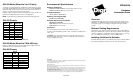
EIA-422 Pinouts
*EIA-232 signals on EtherLite EIA-422 only
EIA-485 Mode (EtherLite 2 EIA-485 only)
EtherLite 2 EIA-485 ports are wired for half duplex multiple drop EIA-
485 mode and have no termination installed.
EIA-485 Pinouts
Environmental Specifications
Operating Temperature
32°F (0°C) to 122°F (50°C) for units with less than 32 ports
32°F (0°C) to 95°F (35°C) for 32-port units
Storage Temperature
-13°F (-25°C) to 167°F (75°C)
Operating or Storage Humidity
0 to 90% non-condensing
AC Power Requirements (maximum)
100-240 VAC, 50-60 Hz
15W (15VA) for units with less than 32 ports
25W (25VA ) for 32-port units
Power Cord
The recommended power cord for North American units is:
UL Listed, CN, detachable type SJT or SVT, 3 conductor, 18 AWG, rated
125 V, 10 A.
CAUTION: To prevent electric shock, do not remove the cover of an
EtherLite module. There are no user-serviceable parts inside. Refer ser-
vicing to qualified personnel.
Copyright
The Digi logo and EtherLite are registered trademarks of Digi International. All other brand and product
names are trademarks of their respective holders.
© Digi International Inc., 2000
All Rights Reserved
Information in this document is subject to change without notice and does not represent a commitment on
the part of Digi International.
Digi provides this document “as is”, without warranty of any kind, either expressed or implied, includ-
ing, but not limited to, the implied warranties of fitness or merchantability for a particular purpose. Digi
may make improvements and/or changes in this manual or in the product(s) and/or the program(s)
described in this manual at any time.
This product could include technical inaccuracies or typographical errors. Changes are periodically made
to the information herein; these changes may be incorporated in new editions of the publication.
EtherLite
Hardware
Information Guide
Overview
Digi EtherLite serial port servers connect asynchronous serial ports to
10BASE-T and 100BASE-T Ethernet connections. Most EtherLite serv-
ers support speeds up to 115 Kbps or 230 Kpbs on all ports simulta-
neously.
Ethernet Cabling Requirements
The EtherLite unit requires an unshielded twisted-pair (UTP) 10Base-T
Ethernet or 100Base-TX connection. In order to maintain radio frequency
emissions compliance, use EIA/TIA 568-compliant Category 4 or Cate-
gory 5 for 10Base-T and Category 5 only for 100Base-TX.
Installing the EtherLite Software
Install the hardware before you install the device driver software. Follow
the software installation instructions on the Access Resource CD.
Signal
RJ-45
Pin
Direction
RTS* 1
RxD(-) 2 input(-)
DCD* 3
RxD(+) 4 input(+)
TxD(+) 5 output(+)
SG 6
TxD(-) 7 output(-)
CTS* 8
Signal
RJ-45
Pin
Direction
No connect* 1
No connect* 2
No connect* 3
TX(A)/RX(A) 4 Bidirectional
TX(B)/RX(B) 5 Bidirectional
GND 6
No connect* 7
No connect* 8
*Do not connect any signal.