USB Plus Series Installation Guide (90000410 Rev. C) – Page 3
Hubport/PCI+ and Hubport/PCI+ LP (Low Profile)
Hubport/PCI+ is a USB 2.0 full size expansion card with powered USB technology. The Hubport/PCI+ card is
available in two versions. The externally powered card utilizes a 24 volt external power supply. The internally
powered card utilizes power balancing technology to provide maximum power to 12 volt and 24-volt peripherals
without exhausting the PC’s 5 or 12 volt power. Port 1 supplies 24 VDC, and Ports 2 through 4 supply 12 VDC (in
addition to the standard 5 VDC available in all of the PlusPower ports as shown in figure 1 on page 1).
The Hubport/PCI+ LP product refers to two USB 2.0 low profile expansion cards with powered USB technology:
the active card, which has 3 ports, and the passive card, which has 1 port. The active card is managed and the
passive card can be either managed or not managed, depending on how it is installed (as described in step 6 below).
“USB Plus Series Interface” on page 6 and “Edgeport Utility Program” on page 7 describe in detail management of
the Hubport/PCI+.
All of the USB ports have cable locking mechanisms to ensure a secure connection to PlusPower peripheral devices.
These ports are also keyed to ensure that they can be connected only to a USB plug designed for their specific power
rating. See Figure 1 on page 1 for a diagram of the different keys.
Installing the Hubport/PCI+
1) Discharge any static electricity from your body by touching a grounded metal object (such as the exposed
metal parts on the back of your computer) before handling your Hubport/PCI+ card.
2) Turn off power to the computer and disconnect the power cord.
3) Open the computer cabinet. See your computer documentation for specific instructions, if needed.
4) Locate an unused PCI expansion slot and remove the expansion slot cover. Save the slot cover screw for use
in Step 5.
5) Insert the USB PlusPower adapter in the PCI expansion slot. Press the adapter firmly into the slot until it
clicks into place. Replace the slot cover screw. When installed properly, the adapter should be level with the
expansion slot.
6) Attach an available hard drive power cable into the connector on the back of the Hubport/PCI+ card or
Hubport/PCI+ LP active card (if using separately or together) or the Hubport/PCI+ LP passive card (only if
using separately). If none are available, you may need to purchase a standard Y-connector.
7) For the Hubport/PCI+ LP passive card only
: This board has no controller and must be connected to another
controller: either to the Hubport/PCI+ LP active card (managed) OR via USB to the PC (unmanaged).
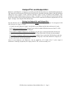
a) Managed: Plug the ribbon cable on the active card
into the receptacle on the passive card, making sure that
the notches match. (See picture at right.)
b) Unmanaged: Plug one end of a USB cable in to the
card and the other end into the PC.
8) For externally powered cards only
, plug the 24 volt
power supply into the card and tighten the locking
screw.
9) Close the computer cabinet and reattach the power cord.
10) After restarting your computer you may continue with driver installation.


