USB Plus Series Installation Guide (90000410 Rev. C) – Page 6
USB Plus Series Interface
(for Hubport/4c+ and the managed Hubport/PCI+ and Hubport/PCI+ LP cards)
The USB Plus Series products present themselves to a user application by way of a virtual serial port. This serial
port is named as all standard serial ports in the form of COMx where x is a number between 1 and 255. The number
assignment can be configured using the Edgeport configuration utility. (See the “Edgeport Utility Program” section
for more information about using this utility.)
There are two ways to manage the power on these devices: You can either use an ASCII command interface to send
commands to the Power Management COM port, as described in this section, or you can use the Edgeport Utility
program (see page 7).
All ASCII commands sent to the device must be terminated with a carriage return character <CR>.
The format of the response sent from the USB Plus Series product to the application is an ASCII printable character
string terminated by a <CR>.
Other response strings generated by the USB Plus Series product include Invalid Command <CR>.
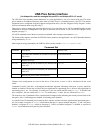
Command Set
Command Description Return Value
?<CR>
Tells about the command set available for the USB
Plus Series.
as described herein
I<CR>
Displays port type.
Power Management Port<CR>
Eh<CR>
Enables port power as defined by the hexadecimal
value of h.
OK<CR>
Dh<CR>
Disables port power as defined by the hexadecimal
value of h
OK<CR>
S<CR>
Returns port power status in hexadecimal.
h<CR>
Changes to the configuration are saved in the device. If the device is reset, it will be initialized with the saved
values.
Commands D and E each have a bit-mapped hexadecimal argument indicating which port, or ports, should be
enabled or disabled. The bit map will have the least significant bit representing port 1, the next least significant bit
representing port 2, etc. For example, to enable port 1, the user would send the string 'E1<CR>'. To disable both
port 1 and port 3, the user would send 'D5<CR>'. To enable ports 1, 2, and 4, the user would send 'EB<CR>'.
The response to the S command will be a hexadecimal bit-mapped value indicating the current powered state of the
four ports, with a 1 indicating power enabled, 0 indicating power disabled.
As with the D and E commands, the bit map for the S response will have the least significant bit representing port 1,
etc. For example, a response of '4<CR>' would indicate that port 3 is power enabled, and ports 1, 2, and 4 are power
disabled. A response of 'E<CR>' would say that ports 2, 3 and 4 are enabled, and port 1 is disabled. A response of
'0<CR>' would indicate that all ports are power disabled.


