


Part number: 64-0099-03
Dialogic
®
D/480JCT-2T1-EW
Installation Guide
Copyright © 2006-2008 Dialogic Corporation.
All rights reserved.
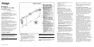
1. Product Description
The Dialogic
®
D/480JCT-2T1-EW combined media
board provides up to 48 channels of voice and
media resources and two T1 telephony interfaces in
a single full-length PCI Express slot.
Additional Information
Additional information about the Dialogic
®
D/480JCT-2T1-EW board is available from a
number of sources.
The product data sheet, available at
http://www.dialogic.com/products, provides a
functional description as well as information about
applications and configurations, features, and
technical specifications.
Refer to the Release Guide and the online Release
Update for your Dialogic
®
System Software release
to verify that the Dialogic
®
D/480JCT-2T1-EW
board is supported in the release, and for
information on any new features or issues that may
relate to it.
The Regulatory Notices document that is packed
with each Dialogic
®
D/480JCT-2T1-EW board
contains safety warnings and national
requirements for proper operation of
telecommunications equipment.
2. Before You Begin
Protecting the Board from Damage
CAUTION: All computer boards are sensitive to
electrostatic discharge (ESD). Handle all
static-sensitive boards and components at a
static-safe work area, and observe anti-static
precautions at all times.
If you are not familiar with ESD safety precautions,
visit http://www.dialogic.com/support/hwinstall to
learn more.
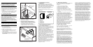
Unpacking the Board
Unpack the board according to the following steps:
1. Prepare a static-safeguarded work area.
2. Carefully remove the board from the shipping
carton and static-shielding bag. Handle the
board by the edges and avoid touching the
board's components.
3. Lay the board on the static-dissipative work
surface.
Note: Place boards in static-shielding bags when
carrying boards from station to station.
CAUTION: Do not remove the board from the
anti-static packaging until you are ready to install
it. Observe proper anti-static precautions at all
times.
3. Configuring the Board
The Dialogic
®
D/480JCT-2T1-EW board uses Plug
and Play technology to simplify installation. No user
configuration is required for IRQ or memory
address.
The Dialogic
®
D/480JCT-2T1-EW board has three
manually configurable items:
■
Board ID
■
CT Bus termination
■
Remote loopback mode
■
Power budgeting (see Choosing a Slot section
below)
Setting the Board ID
When the system is started, each Dialogic
®
telecom board is assigned a board instance ID
number that programs can use to identify
individual boards in a multi-board system. The
setting of SW100 controls the generation of the
instance numbers.
Windows Systems: In a Windows system, leaving
SW100 set to the 0 position (the factory default
setting) on all Dialogic
®
telecom boards causes
the system software to assign instance numbers
geographically, based on the bus and slot
numbers. Note that when using this method,
there is no way to know what the instance
numbers will be until the system is started and
configured, and the instance number for any
given board is likely to change when there is any
change in the number or arrangement of boards
in the system.
As an alternative, you may set SW100 on each
board to a different position (0-9 or A-F) to
explicitly assign specific ID numbers to the
boards. Note that each board must be set to a
different ID number.
In either case, you can read the ID numbers
assigned to the boards in the Dialogic
®
Configuration Manager (DCM) after you start the
system and invoke that tool.
Linux Systems: In a Linux system, you must
explicitly specify the board ID numbers by
setting SW100 on each board to a different
position (0-9 or A-F). Refer to the Configuration
Guide for Springware architecture products in
your Dialogic
®
System Software documentation
for further information about the board ID
numbers.
Setting the CT Bus Termination
Note: If you are using this product by itself and
not connecting it to other telephony boards via a
CT Bus cable, you do not need to set the CT Bus
termination jumpers.
Jumpers are used to terminate signals on the CT
Bus. These settings apply to boards located at
physical ends of the bus. For CT Bus or SCbus, the
signals CT_C8_A, CT_C8_B, CT_FRAME_A*, and
CT_FRAME_B* are terminated using pins 3 and 4 of
the P700 termination jumpers. For MVIP, C_2 and
C_4* are terminated using pins 1 and 2 of the P700
termination jumpers. Bus signals are terminated
when a jumper clip is installed over the indicated
pins.
Note: Only the two boards at each end of the CT
Bus ribbon cable must have their terminations
enabled. All other boards must not have the
jumper clips installed.
Setting Remote Loopback Mode
The Dialogic
®
D/480JCT-2T1-EW board is shipped
with SW500 and SW600 set for normal operation,
with the switch sliders in the position closer to the
board’s bracket. Setting either switch to the
opposite position selects the loopback mode for the
corresponding network interface and overrides any
board modes set by your application. Loopback
mode is commonly used to check the network
connection after the firmware has been
downloaded to the board.
4. Choosing a Slot
The Dialogic
®
D/480JCT-2T1-EW board is a full
length x1 form factor PCI Express board that
requires 25W of power. The following explanation
and guidelines are provided to ensure proper
configuration of the product.
Power Budgeting is a new feature, introduced in
the PCI Express Specification, that provides a
mechanism to enable a system to negotiate power
consumption requirements for add-in devices.
Per PCI Express Card Electromechanical
Specification Revision 1.0a or higher, a x1 add-in
card can draw no more than 10W in a x1 slot
unless the board’s required power is successfully
negotiated and allocated by the system (power
budgeting). However, implementation of power
budgeting by a vendor's system is not a compliance
requirement per the PCI Express Card
Electromechanical Specification Revision 1.0a or
higher. Therefore, some chassis may not support
this feature. Power Budgeting jumper P3 is
designed to ensure proper configuration of the
product.
The Dialogic
®
D/480JCT-2T1-EW board must be
installed in a slot that can be allocated 25W.
If Power Budgeting is not implemented by a
vendor's system, the Dialogic
®
D/480JCT-2T1-EW
board must be plugged into a x4 or higher slot
with the P3 jumper in position 1-2 (power
budgeting ignored). This is allowed per PCI Express
Card Electromechanical Specification Revision 1.0a
or higher because a x4 or greater slot must be able
to support a minimum of 25W.
If Power Budgeting is implemented by a vendor's
system, the Dialogic
®
D/480JCT-2T1-EW board
can be plugged into a x1 slot but the P3 jumper
must be in position pins 2-3 (power budgeting
adhered to).