


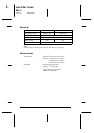
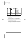
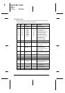
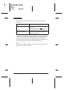
Signal
Pin
Return
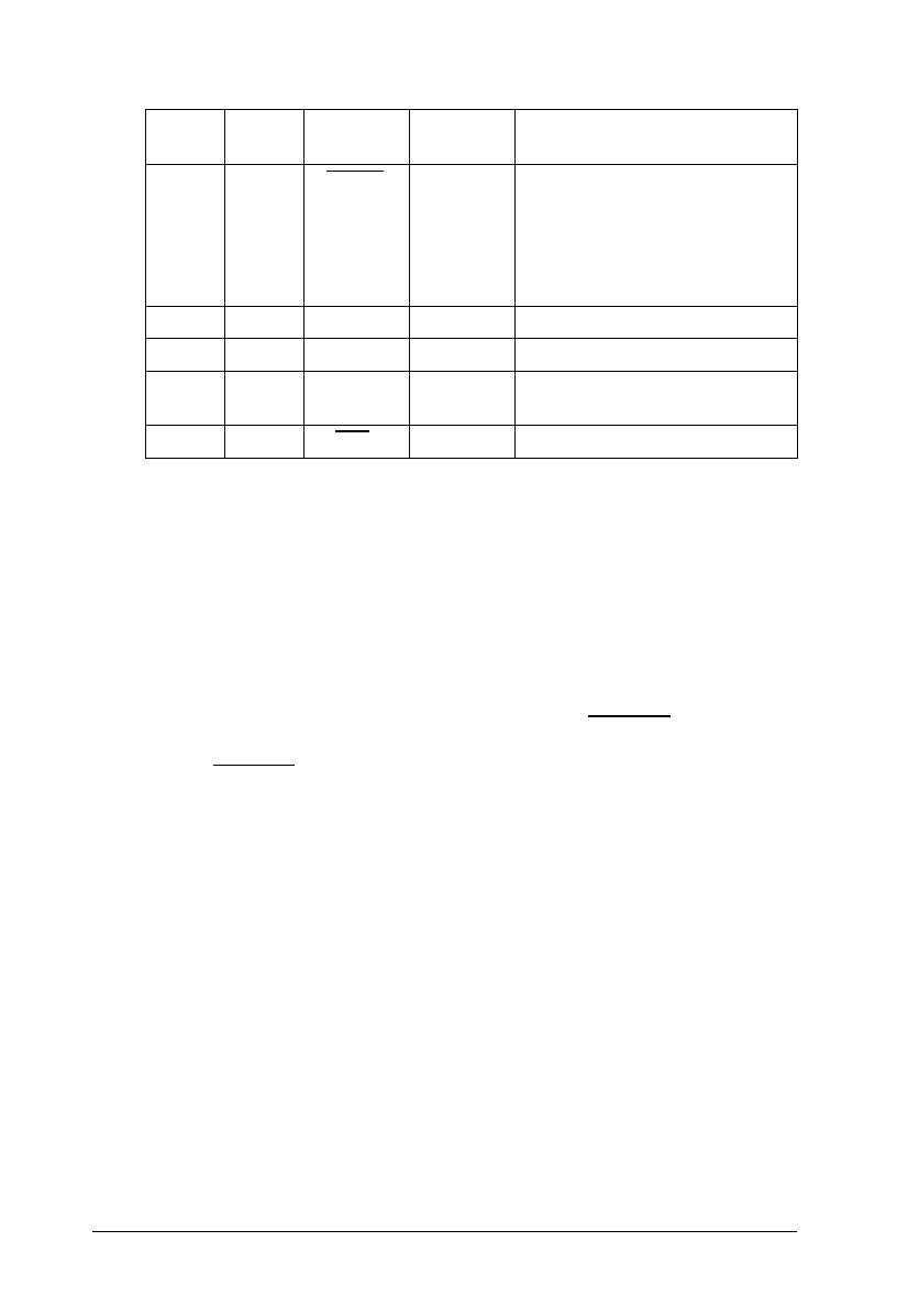
Pin Signal Direction Description
32 29
ERROR OUT This signal level goes LOW
when the printer:
1) Is out of paper
2) Has jammed paper
3) Is in an error state
4) Is out of ink
33 - GND - Same as for Pins 19-30
34 - NC - Not used
35 - +5 V OUT Pulled up to +5 V through
3.3 KΩ resistance
36 30
SLIN IN Not used
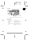
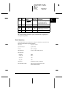
Note:
❑
The column heading “Direction” refers to the direction of signal flow as
viewed from the printer.
❑
“Return” denotes the twisted-pair return to be connected at signal ground
level. For the interface wiring, be sure to use a twisted-pair cable for each
signal and to complete the connection on the return side.
❑
All interface conditions are based on TTL level. Both the rise and fall times of
each signal must be less than 0.2 microseconds.
❑
Data transfer must be carried out by observing the ACKNLG or BUSY
signal. Data transfer to this printer can be carried out only after receipt of
the
ACKNLG signal or when the level of the BUSY signal is LOW.
L
Loire2 Ref. Guide
Rev.c
A5 size Appendix C
11-11-96 DR, pass 0
C-16
Specifications