LBI-39224
3-147
match the switch assignment number set by the DIP switches on the
MOM Controller Board. See CEC/IMC Digital Audio Switch
Installation, Set-Up And Troubleshooting (LBI-38938) for MOM
Controller Board DIP switch configuration details.
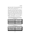
Table 5 maps the conventional channel allocation numbers in a
StarGate network when the maximum number of conventional channels
per CEC/IMC is set to sixty-four (64). Table 6 shows the mapping for
thirty-two (32) maximum channels per CEC/IMC. As shown in these
tables, the conventional channel allocations recycle with higher switch
assignment numbers. Therefore, when assigning switch assignment
numbers, ensure the conventional channel allocations are unique at each
CEC/IMC. For example, conventional channels should not be installed
at CEC/IMC 33 and CEC/IMC 37 if the maximum number of
conventional channels per CEC/IMC is equal to sixty-four (64).
Similarly, conventional channels should not be installed at
CEC/IMC 33 and CEC/IMC 41 if the maximum number of
conventional channels per CEC/IMC is equal to thirty-two (32).
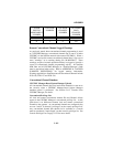
Table 5 Switch Assignment Number-to-Conventional Channel
Allocation Mapping for StarGate Networks (Max. Conv. Channels
per CEC/IMC = 64)
CEC/IMC SWITCH
ASSIGNMENT NUMBERS
CONVENTIONAL CHANNEL
ALLOCATIONS
33
, 37, 41, 45, 49, 53, 57, 61
1 – 64
34
, 38, 42, 46, 50, 54, 58, 62
65 – 128
35
, 39, 43, 47, 51, 55, 59, 63
129 – 192
36
, 40, 44, 48, 52, 56, 60, 64
193 – 255
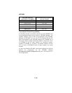
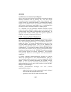
Table 6 Switch Assignment Number-to-Conventional Channel
Allocation Mapping for StarGate Networks (Max. Conv. Channels
per CEC/IMC = 32)
CEC/IMC SWITCH
ASSIGNMENT NUMBERS
CONVENTIONAL CHANNEL
ALLOCATIONS
33
, 41, 49, 57
1 – 32
34
, 42, 50, 58
33 – 64
35
, 43, 51, 59
65 – 96


