LBI-39224
3-200
the Backplane. The MOM Controller Board controls clock selection by
sending clock select command signals to all other Controller Boards
within the CEC/IMC. Each Controller Board then controls the clock
select circuitry on its respective Audio Boards.
The redundant clock feature should only be enabled if the
CEC/IMC is equipped with Audio Boards 19D903302P1 Rev.
K (and later) and/or 19D903302P3. DO NOT enable the
redundant clock feature if the CEC/IMC uses 19D903302P1
Rev. J or earlier Audio Boards.
If any of the selected clock pulses fail ("A" or "B" clock), clock
monitoring circuitry on the Audio Boards signals their respective
Controller Board. The informed Controller Boards then signal the
MOM Controller Board, and if the redundant clock feature is enabled,
the MOM Controller Board then commands all other Controller Boards
in the CEC/IMC to switch their Audio Boards to the other clock circuit.
Redundant Clock Configuration
The initial start-up or default clock circuit is "B." If the MOM and two
other Controller Boards report a "B" clock circuit problem, the MOM
will switch clock operation to the "A" clock. Similarly, the MOM will
also switch back to the "B" clock if a problem exists with the "A" clock.
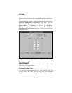
This redundant clock circuit selection can be enabled and disabled at
the CEC/IMC Manager.
If two or more Clock Boards are installed, corresponding
clocks on the different Clock Boards should never be turned
on ("A" and "A" for example). If only a single Clock Board is
installed, both clocks should be turned on when the redundant
clock feature is enabled ("A" and "B").
Panel-mounted toggle switches on the Clock Boards allow independent
enable/disable control of the FUTUREBUS transceivers so multiple
NOTE
NOTE


