LBI-39224
3-60
slightly, and the changes become more pronounced the further the
signal travels down the line. The outgoing original signal is modified
based upon line length so that the signal arriving at the destination
closely resembles an ideal signal. Select the line length from the drop-
down list box for T1 applications. E1 applications do not support
selectable line lengths.
Set Site Channel Disbursement
The Set Site Channel Disbursement field sets the number of channels
assigned to the indicated T1/E1 Interface Card. Enter the number of
channels in the text box (1 - 24 for T1 or 1 - 31 for E1).
Select Slave Clock Mode
Selecting the Slave Clock Mode is part of a higher level system design,
as mentioned earlier. Any system nodes that are connected using T1/E1
Interfaces must remain frequency locked at all times. The T1/E1
Interface design allows for total network synchronization through
different CEC/IMC configuration options. A detailed discussion of the
higher level system configuration is beyond the scope of this topic;
however, for a more detailed discussion refer to T1/E1 Interface
Release Notes (350A1909) and CEC/IMC Digital Audio Switch
Installation, Set-up, and Troubleshooting (LBI-38938). Select the
required clock mode from the drop-down list box.
View
Choose the
View
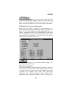
button to display the T1/E1 Interface Card Auto-
configuration dialog box, which shows the T1/E1 channels and subrate
port configurations.
Read Disk
Choose the
Read Disk
button to view the currently stored
configuration on the CEC/IMC Manager hard disk. This normally
should be the same as the actual configuration at the CEC/IMC.
Read MSC
Choose the
Read MSC
button to view the actual configuration at the
CEC/IMC (stored in the interface module's NOVRAM). This normally
should be the same as the configuration stored on the CEC/IMC
Manager hard disk. If the CEC/IMC Manager hard disk data was
cleared or reset to undesired values,
Read MSC
followed by
Save
will restore the CEC/IMC Manager hard disk configuration.


