


1 © 2008 Extreme Networks, Inc. All rights reserved. Part Number 100293-00 Rev 02 2
Altitude 802.11n (450/451) AP Installation Instructions
Altitude 802.11n (450/451) AP Installation Instructions
Unpacking and mounting the Altitude 802.11n AP
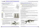
The Altitude 802.11n AP has two models:
• Altitude 450: 3 internal antennas
• Altitude 451: 3 external antennas, RP-SMA connectors
Unpack the Altitude 802.11n AP from its carton. Also in the carton
are:
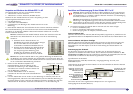
• one wall mounting bracket
• 3 screws and 3 wall plugs
• one plastic rivet (Save this rivet to secure the Altitude 802.11n AP to
the bracket.)
• For the Altitude 451, the three external antennas are also
included.
An additional security bracket can be purchased that provides port
protection and cable management. For more information, contact your Extreme Networks
®
representative.
Note: For the Altitude 451, attach the three antennas to the RP-SMA connectors on
the Altitude 802.11n AP before mounting on its bracket.
Note: The bracket shipped with the Altitude 802.11n AP is identical to the bracket
used with the Altitude 35x/36x models. If you replace an Altitude 35x/36x AP
with the Altitude 802.11n AP, you can mount the AP on the existing wall bracket.
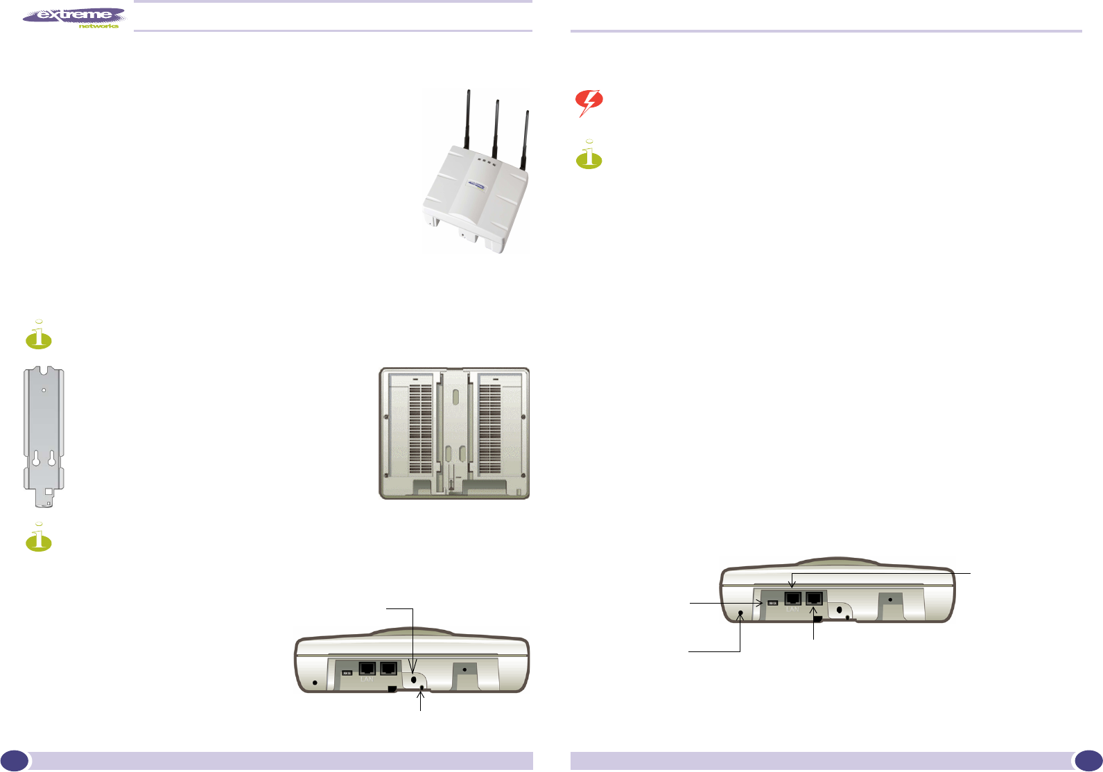
3 Using a screwdriver, insert the plastic rivet through the hole at the bottom of the
bracket and into the Altitude 802.11n AP case. This locks the case to the bracket.
4 To remove the Altitude 802.11n AP, use a
screwdriver to take out the rivet.
5 To remove the Altitude 802.11n AP, release
the spring clip by inserting an Allen key
(or other similar tool) into the small hole at
the bottom of the bracket. Then slide the
case up the bracket and lift off the Altitude
802.11n AP.
Connecting and powering the Altitude 802.11n AP
Warning: This device must not be connected to a LAN segment with outdoor
wiring. Ensure that all cables are run correctly to avoid strain. Replace the power
supply adapter immediately, if it shows any signs of damage.
Note: Powering up the Altitude 802.11n AP initiates its automatic discovery and
registration process with the Summit WM Controller. The parameters for this
process are configured through the Summit WM Graphical User Interface. For
more information, see the Summit WM User Guide.
6 Power up the Altitude 802.11n AP in one of three ways:
• Power over Ethernet (PoE)
• Power over Ethernet: Adding PoE injector
• Power by AC adaptor
Power over Ethernet (PoE)
If your network is already set up with PoE (802.3af compliant), attach the LAN Ethernet
cable to the RJ45 Ethernet connector in the top of the Altitude 802.11n AP.
Power over Ethernet: Adding PoE injector
If your network is not set up with PoE, you can provide power to the Ethernet cable with a
PoE injector. The PoE injector must be 802.3af compliant. The PoE injector is not provided
with the Altitude 802.11n AP.
Powered by AC Power Module
An optional AC power module can be used to power the Altitude 11n AP from an AC
power source. It can be purchased from Extreme Networks. The part number is 15802. You
need to separately procure a region-specific AC power cord that plugs into the standard
IEC C14 socket in the power module.
Power Module Specifications:
Input: 50-60Hz, 100-240 VAC; Output Voltage 48V DC, Max Amps = 0.38A.
Connect the power module to the Altitude 11n AP and then plug the power module to the
AC outlet.
Use only a safety-approved POE injector or a safety-approved Limited Power Source
(Class 2) AC adaptor.
1 Using the 3 screws, mount the Altitude
802.11n AP wall bracket. Mount it near
the LAN Ethernet cable plug coming
from the wall.
2 Press the back of the Altitude 802.11n AP
onto the bracket, aligning it with the
open notches in the bracket. Then slide it
down until the security spring clip holds
it in place.
Opening for rivet
Opening for Allen key
Console Port
[Optional]. Connect
the AC power module
if PoE is not being
used in your network.
Attach a screw, and
then fasten the
cables using a tie
wrap to the screw to
provide strain relief.
Connect the LAN
Ethernet cable to the
Ethernet port.