


Summit WM Series WLAN Switch Installation Instructions
© 2006 Extreme Networks, Inc. All Rights Reserved. Part number: 120338-00 Rev. 01
Getting Started
These instructions provide installation technicians with a high-
level overview for installing a Summit
®
WM series switch
WM100/WM1000.
Unpack the controller:
1 Lift the controller, in its protective foam casing, straight up
and out of the carton.
2 Lay the controller on a flat surface and slide off the foam
casing.
3 Confirm that your carton contains all of the appropriate
content.
Carton contents:
● One controller
● Two mounting brackets
● Eight 6-32 X 3/8 countersunk machine screws
● One power cord (two for dual power supply version)
● One crossover RJ45 Ethernet cable (for installation)
● One ferrite bead for the Management card Ethernet cable
(models WM100/WM1000)
● Summit WM Series WLAN Switch Installation Instructions
(English and German)
● Summit WM Series WLAN Switch and Altitude Access Point
Software Version 4.0 User Guide (CD)
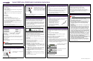
Step 1 – Mount
Two mounting options are available, rack and table.
Rack mounting:
Attach the mounting brackets to the controller in the appropriate
position for the type of rack to be used, and then attach the
brackets to the rack.
Table mounting:
Ensure at least 2 inches of clearance on all sides of the controller
for proper ventilation.
WARNING!
Do not obstruct the air intake vent on the front, or the side and rear
ventilation grills of the controller.
Step 2 – Connect to a power supply
Two types of power supply are available, redundant and
standard.
Standard power supply:
Connect the power cord (supplied)
to the controller.
Connect to a power supply
Redundant power supply:
Connect the two power cords
(supplied) to the controller. The LEDs
on the power supply will be lit green.
If only one power cord is connected,
the power supply sounds a warning.
Power off the controller:
To power off the controller, hold the on/off switch in the off
position for at least 5 seconds.
Step 3 – Configure the controller
Before you connect the controller to the enterprise network,
change the IP address of the controller Management port from its
factory defaults to the IP address suitable for the enterprise
network. Access the controller by one of two methods:
● Use a device supporting VT100 emulation, attached to the
Console port (supports a 9600 baud rate) of the controller via
a crossover (null modem) cable. Use the Command Line
Interface (CLI) commands.
● Use a laptop computer with a browser. Connect the crossover
Ethernet cable between the laptop and Management Ethernet
port of the controller. Follow the steps below.
1 Statically assign an unused IP address in the 192.168.10.0/24
subnet for the Ethernet port of the computer.
2 Launch your Web browser, and in the browser address bar,
type https://192.168.10.1:5825. This launches the Summit
Wireless Assistant. The logon screen appears.
3 In the User Name box, type admin, and in the Password box,
type abc123.
4 Click Login.
5 From the main menu, click Summit Switch Configuration.
6 In the left pane, click IP Addresses.
7 In the Management Port Settings section, click Modify.
8 Type the following information:
● Hostname – The name of the controller
● Domain – The IP domain name of the enterprise network
● Management IP Address – The new IP address for the
controller’s Management port. Change this as appropriate
for the enterprise network.
● Subnet mask – The appropriate subnet mask for the IP
address to separate the network portion from the host
portion of the address (typically 255.255.255.0)
● Management Gateway – The default gateway of the
network
● Primary DNS – The primary DNS server used by the
network
● Secondary DNS – The secondary DNS server used by the
network
9 To save your changes, click OK.
Configure the controller
The Web connection between the computer and the controller is
now lost. The IP addresses are now set to the network you
defined.
1 Disconnect your computer from the controller Management
port.
2 Connect the controller Management port to the enterprise
Ethernet LAN. The controller resets automatically.
3 Log on to the Summit Wireless Assistant. The system is
visible to the enterprise network.
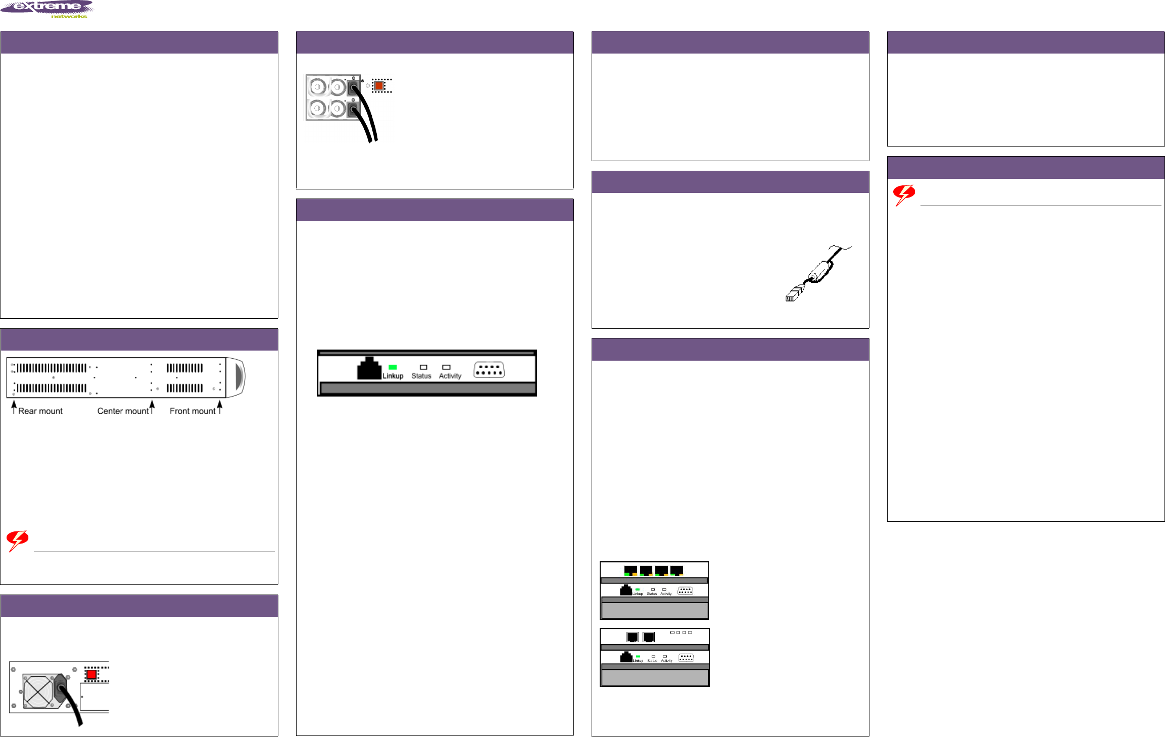
Step 4 – Connect the ferrite bead
1 Install the ferrite bead on the Management card Ethernet
cable.
2 Install the ferrite bead no further than 4 inches away from the
RJ45 Ethernet connector at the back of the controller.
3 Place the cable through the ferrite
bead, wrap it back around the
outside of the bead and once again
through the bead (1 1/2 turns
around the bead), as shown here.
4 Snap the two halves of the bead
firmly together without pinching
the wire insulation.
Step 5 – Configure your system
These six steps provide a high-level overview for configuring
your system. For more detailed information, see the Summit WM
Series WLAN Switch and Altitude Access Point Software Version 4.0
User Guide.
1 – Before you begin configuration:
Research the type of WLAN deployment that is required.
2 – Prepare the network:
Ensure relevant DHCP servers and RADIUS servers (if
applicable) are available and configured.
3 – Configure the physical port IP:
● Configure the default IP address to be the relevant subnet
point of attachment to the existing network, and setup the
routing protocol and table. The default IP address is 10.0.#.1.
● To configure a physical port to attach to a VLAN, define the
VLAN as part of the IP address assignment.
4-port RJ45 version 10/100 BaseT
(models WM10/WM100)
2-port MT RJ version (model
WM1000) GigE
4 – Configure the VNS:
Research and configure the traffic topologies the network will
support.
Configure your system
5 – Confirm the AP firmware version:
Confirm the latest firmware version is loaded.
6 – Install, register, and assign APs to the VNS:
● Deploy APs to their corresponding network locations.
● For information on installing and powering the wireless APs,
see the Summit WM Series WLAN Switch Installation
Instructions.
Safety Information
WARNING!
Warnings identify information that is essential. Ignoring a warning can
adversely affect the operation of your equipment or software.
● Only authorized Extreme Networks service personnel are
permitted to service the system.
● Use only original accessories or components approved for
the system. Failure to observe these instructions may
damage the equipment or even violate safety and EMC
regulations.
● This device must not be connected to a LAN segment with
outdoor wiring.
● This unit may have more than one power supply cord. To
avoid electrical shock, disconnect all power supply cords
before servicing. In the case of unit failure of one of the
power supply modules in the Redundant Power Supply
version, the module can be replaced without interruption of
power to the controller. However, this procedure must be
carried out with caution. Wear gloves to avoid contact with
the module, which will be extremely hot.
● Disconnect all power before working near power supplies
unless otherwise instructed by a maintenance procedure.
● Exercise caution when servicing the hot swappable power
supply of the controller (WM100/WM1000).
● Check the nominal voltage set for the equipment (operating
instructions and type plate). High voltages capable of
causing shock are used in this equipment.
● For system regulatory information, see the Summit WM
Series WLAN Switch and Altitude Access Point Software
Version 4.0 User Guide.