This guide provides instructions for an experienced installer to set up and operate Extron® DVI-RGB 200
DVI to Analog RGB Video Interface.
Installation
Step 1 — Mounting
Turn off or disconnect all equipment power sources and mount the interface as required.
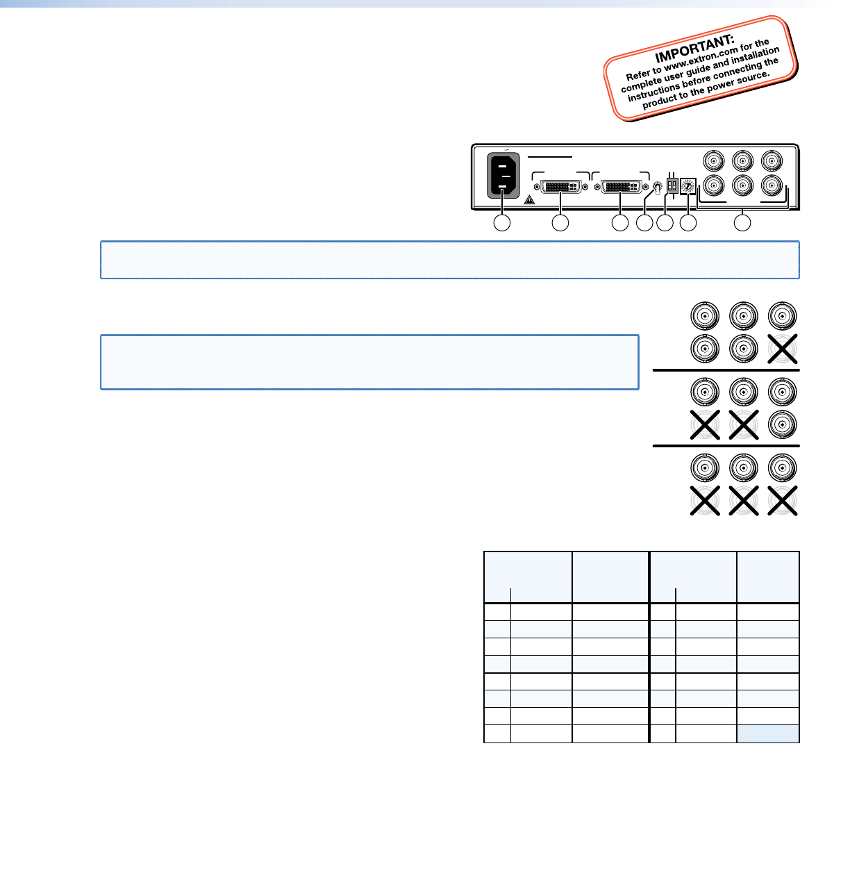
Step 2 — Connections and Initial Settings
a
DVI-D Input connector — Connect a single link of direct
digital video to this DVI-I connector using the included cable.
b
Buffered Loop-through connector — If desired, connect a
direct digital local monitor to this DVI-I connector.
NOTE: Use only cables specifically intended for DVI interfaces. Use of non-DVI cables or modified cables can cause
the DVI-RGB 200 to not operate correctly.
c
Output connectors — Connect an RGB display to these female BNC connectors. Connect the
BNCs as shown at right for the desired RGB video format.
NOTE: Ensure that the SOG DIP switch (
f
) is turned off (down) for RGBHV and RGBS
video.
Ensure that the SOG DIP switch is turned on (up) for RGsB video.
d
EDID Source switch —
Set this switch to the Monitor (up) position to connect the DDC channel between the direct
digital video source and the local monitor.
Set this switch to the Selector (down) position to connect the DDC channel between the
direct digital video source and the built-in DVI-RGB 200 EDID logic.
e
EDID Select — If the EDID Source switch (
d
) is in the Selector (down) position, set this switch
to the appropriate position to select the desired video resolution. Use the Refresh DIP switch
(
f
) to select the refresh rate. The table at right identifies the
switch positions and the associated resolutions and vertical
refresh rates.
f
DIP switches —
SOG (Sync on Green) On/Off switch — Set this switch to the
On (up) position to enable SOG for RGsB video. Set this switch
to the Off (down) position to disable SOG for RGBS or RGBHV
video.
Refresh switch —
If the EDID Source switch (
d
) is in the Selector position (down)
and the EDID select switch (
e
) is in position 1 through F
position, set this switch either up or down to select the refresh
rate of the selected output. See the table at right.
If the EDID Source switch (
d
) is in the Selector (down) position and the EDID select switch is in position 0, set this switch
up to capture the EDID data from the connected Buffered Loop-through monitor. See Capturing a User-recorder EDID.
g
AC power connector — Plug a standard IEC power cord into this connector to connect the interface to a
100 to 240 VAC, 50 Hz or 60 Hz power source.
100-240V 0.4A
OUTPUT
DVI-D INPUT
BUFFERED
LOOP-THROUGH
R
H
G
V
B
S
SOG ON/OFF
REFRESH
EDID
SOURCE
MONITOR
HIGH
LOW
SELECTOR
EDID
SELECT
DVI-RGB 200
50/60 Hz
21 57 3
64
R
H
G
V
B
S
R
H
G
V
B
S
R
H
G
V
B
S
RGBHV
RGBS
RGsB
Pos. Resolution
EDID Select
Switch
Refresh
DIP Switch
0 User EDID EDID capture
1
2 1024x768
3 1280x720
50 Hz 60
50 Hz 60
50 Hz 60
4
5
1280x768
1280x800
50 Hz 60
50 Hz 60
800x600
<
>
Dwn Up
8
9
A
B
1366x768
1400x1050
Pos. Resolution
50 Hz 60
50 Hz 60
C
D
1440x900
1600x1200
50 Hz 50
50 Hz 60
6
7
50 Hz 60
50 Hz 60
E
F
50 Hz 50
50 Hz 60
50 Hz 60
Refresh
DIP Switch
<
>
Dwn Up
EDID Select
Switch
1280x1024
1360x768
1680x1050
1920x1080
1920x1200
N/A
1
DVI-RGB 200 Setup Guide


