The role of the technical administrator in today’s schools and
businesses has expanded to include management and
maintenance of A/V devices fr
om multiple manufacturers, often
spread out over great distances. IP Link makes it easier to integrate
A/V systems into existing IP networks, providing Web-based
monitoring and control that unifies A/V equipment under a single
common graphical user inter
face.
The IPL T SF24 and IPL T SFI244 use Extron’s exclusive IP Link
™
technology, a high performance intelligent network solution
specifically engineered to meet the needs of professional A/V
environments, from large universities and businesses to small
presentation environments.
At its core, each IP Link Ethernet control interface is a complete,
high performance, Web server with robust computing power. Each
one contains a very fast processor with a latency, or delay, of less
than one millisecond from the time it receives a command to the
time it acts on that command. As a result, Web pages are served
many times faster than similar products, so data is refreshed at a
consistently high speed. The core technology and high
performance architecture of IP Link interfaces makes them ideal for
implementing A/V system management over the most widely
available transport medium today, the corporate IP network.
Centralized Asset Management and Monitoring
Using IP Link hardware along with the Global Viewer Web-based
asset management application, a technical administrator can track
the activity and status of all connected A/V devices. Multiple
rooms of equipment can be viewed simultaneously, by location or
device type. IP Link makes up-to-the-minute data available like
serial numbers, maintenance history, usage data, current status,
and installed firmware, all viewable from any computer on the
network. With IP Link’s e-mail functionality, accessed via the Global
V
iewer, devices can be configured to proactively manage
themselves. For instance, a pr
ojector can be polled r
outinely to
track lamp usage and total life time. When lamp usage reaches a
pr
edeter
mined number of hours, the IP Link inter
face can send an
e-mail, reminding technicians to replace the lamp.
Automated Scheduling
IP Link interfaces include a real-time clock, allowing an
administrator to program operating alerts, schedule routine
equipment activity, or run maintenance checks on lamp hours,
envir
onmental conditions, connectivity, and other issues vital to
Extron Electronics, USA
1230 South Lewis Street
Anaheim, CA 92805
800.633.9876 714.491.1500
FAX 714.491.1517
Extron Electronics, Europe
Beeldschermweg 6C
3821 AH Amersfoort, The Netherlands
+800.3987.6673 +31.33.453.4040
FAX +31.33.453.4050
Extron Electronics, Asia
135 Joo Seng Rd. #04-01
PM Industrial Bldg., Singapore 368363
+800.7339.8766 +65.6383.4400
FAX +65.6383.4664
Extron Electronics, Japan
Daisan DMJ Bldg. 6F, 3-9-1 Kudan Minami
Chiyoda-ku, Tokyo 102-0074
Japan
+81.3.3511.7655 FAX +81.3.3511.7656
04-03
68-890-01
REV. A
© 2004 Extron Electronics. All rights reserved. All trademarks mentioned are the property of their respective owners.
■ Two serial ports
■ Four Flex I/O ports
■ Four IR por
ts (IPL T SFI244)
■ IR learning capabilities
(IPL T SFI244)
■ Integrated Web server with
1.25 MB of flash memory
■ Multi-user support
■ Multiple levels of security
■ Free IP Link™ Global Viewer
™
Web-based asset management
software
■ IEEE 802.3af Power over Ethernet
(PoE) compliant
IPL T SF24 &
IPL T SFI244
IP LINK
ETHERNET CONTROL INTERFACES
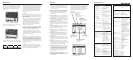
The Extr
on IPL T SF24 and IPL T SFI244 ar
e compact Ether
net contr
ol inter
faces
with integral high per
for
mance W
eb ser
vers, enabling many A/V devices to be
monitor
ed, maintained, and managed over an existing high speed Local Ar
ea
Network (LAN), W
ide Ar
ea Network (W
AN), or the Inter
net.
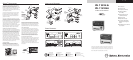
PANEL DRAWINGS
www.extron.com
IPL T SFI244
1
100
COM
TX RX 1 3
2
13
2
I/O IR
IPL T SF24
R
100
LINK
ACT
1
COM I/O
TX
2
RX
RTS
CTS
1234
COM 1
LAN
00-05-A6-xx-xx-xx
POWER
12V
.5A MAX
COM1
TX RX TX RX
I/O
1
234
COM2
COM 2
IPL T SF24 (Front)
IPL T SF24 (Back)
IPL T SFI244
1
R
100
COM
TX
LINK
ACT
2
RX 13
24
13
24
I/O IR
COM1
TX RX TX RX
COM2
LAN
00-05-A6-xx-xx-xx
POWER
12V
.5A MAX
FLEX I/O
2134 1
IR
2 3 4
GSGSGSGS
IPL T
SF24
R
100
LINK
ACT
1
COM I/O
TX
2
RX
RTS
CTS
1
234
COM 1
LAN
00-05-A6-xx-xx-xx
POWER
12V
.5A MAX
COM1
TX
RX TX RX
I/O
1
234
COM2
COM 2
IPL T SFI244 (Front)
IPL T SFI244 (Back)
COM 3
LAN
UID# 093012052
POWER
12V
.5A MA
X
COM 2
1
COM1
TX
RX
TX
RX
I/O
2
3
4
COM2
Lighting
Control
or Lighting
System
Screen
Control
Extron
IPL T RLY4
Relay Box
COM1
TX
RX
TX
RX
COM2
LAN
00-05-A6-xx-xx-
xx
POWER
12V
.5A MA
X
FLEX I/O
2
1
3
4
1
IR
2
3
4
G
S
G
S
G
S
G
S
Lighting
Control
or Lighting
System
Ethernet
RS-232
RS-232
Remote
Monitoring
Scheduling
and Control
Projector
TCP/IP
Network
Extron
IPL T SF24
Ethernet Network
Interface
Motion Detector
Extron
M
e
d
i
a
L
i
n
k
C
o
n
t
r
o
l
l
e
r
ML
C
2
0
6
DISPLAY
POWER
VOLUME
MAX/
MIN
VCR
DVD
Laptop
Screen
Control
Extron
IPL T SFI244
Ethernet Network
Interface
RS-232
RS-232
DVD 1
VCR/
DVD 2
Extron
IR Emitters
Projector
Ethernet
Remote
Monitoring
Scheduling
and Control
Motion Detector
Extron
MLS 103 SV
S-video & Audio
Switcher
DSS Receiver
NO C NC
NO C NC
NO C NC
NO C NC
RELAY
1
RELAY
2
RELAY
3
RELAY
4
MLS 100 Series
MediaLink Switcher
AUX/MIX
LEVEL
INPUT SELECT
1
2
3
4
Extron
MLC 206
MediaLink Controller
TCP/IP
Network
Extron
IPL T RLY4
Relay Box
COM1
TX
RX
TX
RX
COM2
LAN
00-05-A6-xx-xx-
xx
POWER
12V
.5A MA
X
FLEX I/O
2
1
3
4
1
IR
2
3
4
G
S
G
S
G
S
G
S
Lighting
Control
or Lighting
System
Remote
Monitoring
Scheduling
and Control
Screen
Control
Extron
IPL T SFI244
Ethernet Network
Interface
RS-232
RS-232
DVD 1
VCR/
DVD 2
Extron
IR Emitters
Projector
Ethernet
Remote
Monitoring
Scheduling
and Control
Motion Detector
Extron
MLS 103 SV
S-video & Audio
Switcher
DSS Receiver
NO C NC
NO C NC
NO C NC
NO C NC
RELAY
1
RELAY
2
RELAY
3
RELAY
4
MLS 100 Series
MediaLink Switcher
AUX/MIX
LEVEL
INPUT SELECT
1
2
3
4
MediaLink Controller
TCP/IP
Network
APPLICATION DIAGRAMS
IP LINK
™
APPLICATIONS
operations. For instance, an administrator may want to configure
projectors and other devices to power on or off at preset times.
User-defined tasks are easy to configure and schedule with IP Link.
Scheduling tasks and setting up e-mail reminders is simple and
straightforward and doesn’t require high-level programming skills.
Remote Technical Support
One of the biggest challenges facing technical administrators
today is meeting the ever-growing demands for technical support
with limited support staff. IP Link extends the support staff’s reach,
giving technicians the power to troubleshoot and solve many
typical problems remotely. With access to real-time A/V device
status, such as power on or off, and current input selection,
technicians can often restore system operation in minutes. The
result is time saved and a reduced level of frustration for users.
System Security and Loss Prevention
IP Link interfaces are always on and routinely poll their connected
devices for status information. If a serially controlled device like a
projector or document camera is physically disconnected from the
network, the IP Link interface monitoring its status will know
immediately
. In such an event, the IP Link inter
face can be
configured to send an e-mail message notifying security personnel
of the problem.
Extron
IPL T RLY4
Relay box
Lighting System
COM1
TX
RX
TX
RX
COM2
LAN
00-05-A6-xx-x
x-xx
POWER
12V
.5A MA
X
FLEX I/O
2
1
3
4
1
IR
2
3
4
G
S
G
S
G
S
G
S
Screen
Control
Extron
IPL T SFI244
Ethernet Control
Interface
RS-232
RS-232
DVD 1
VCR/
DVD 2
Extron
IR Emitters
Projector
IPL T SFI244 06-03 BW
.eps
Ethernet
TCP/IP
Network
DSS Receiver
NO C NC
NO C NC
NO C NC
NO C NC
RELAY
1
RELAY
2
RELAY
3
RELAY
4
Remote
Monitoring,
Scheduling and
Control
PC
Extron
Global Viewer
Free Web-Based
Management Software
TM
Alarm System
Thermostat
Presentation Room
IPL T SF24
IPL T SFI244
E-mail Message
Theft Alert
Help Desk
Remote Device and Room Control
Theft Alert
Remote Device monitoring, scheduling and
contr
ol using Global V
iewer W
eb-based asset
management application