


PRELIMINARY
1
PCM 340 Installation Notes
The Extron PCM 340 Drop Ceiling Projector Mount is used for
hanging PoleVault
™
System AV products and various projectors.
The PCM is installed above the drop ceiling and secures the
adjustable pipe in a pass-through pipe adapter plate. The pipe
then supports the mounting of the Extron PMK 550 and UPB 25
projector bracket.
C Maximum load for the PCM is 50 lbs (22.7 kg).
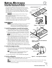
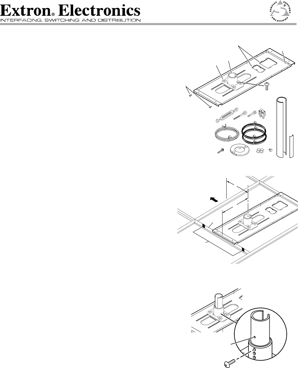
The key components of the PCM 340 are shown in figure 1.
Also included in the kit are:
4 turnbuckles, 5 lag eye bolts, 5 concrete anchors, 2 cable clamps,
1 safety wire – 15 ft., 2 tie wire – 30 ft., 4 T-frame screws, 2 set screws,
1 location screw, 4 adhesive pads, 11 hole plugs, 1 escutcheon ring,
(1) 25 inch slotted projector pipe with 1 snap-in trim piece.
Installation
N Refer to local building standards and codes to verify that the
installation will meet the regulatory requirements.
Observe all local and national building and safety codes,
UL requirements, and ADA Accessibility Guidelines.
1. Install the projector to verify the location.
a. At the predetermined location for the projector, identify the
ceiling tile and T-frame where the PCM will be installed.
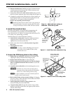
b. Remove the ceiling tile, and mark the projector's maximum
and minimum throw distances on the T-frame (see figure 2).
N
Refer to the projector manufacturer's manual for details.
c. Place the PCM base plate over the T-frame, between the two
marks. Lightly tighten the T-frame securing screws (which
can be inserted on the inside or outside of the PCM).
d. Back out the Pipe Adapter set screws on the adapter plate.
Slide the slotted pipe into the adapter, aligning the holes
in the pipe with those in the adapter (see figure 3). Tighten
the pipe location screw and the set screws to secure the pipe.
e. Install the UPB 25 projector bracket and the projector onto
the end of the pipe. Refer to the UPB 25 User Manual for details.
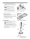
2. Verify the image location.
a. Turn on the projector, loosen the wing nuts and slide the base plate
and projector left and right, viewing the image to verify the proper
location for a centered image.
T Remember to use the vertical and horizontal offsets when
aligning the projector. Adjust pipe height if needed.
Refer to the projector manual for details.
b. When image location is verified, lock down the wing nuts.
3. Cut the ceiling tile.
a. Mark the location of the PCM base plate on the T-frame, before
removing it, to aid in replacing it in the correct location.
T Mark the screen direction on the back of the tile to help with orientation of the tile when replacing it after cutting.
N With assistance, carefully remove the UPB 25 with the projector still attached from the slotted pipe.
Remove the slotted pipe.
PCM 340 Installation Notes
Figure 1 — PCM 340 parts
68-1573-01
Rev B
05 09
Align Pipe holes with
location screw holes.
Insert location screw
and secure.
Figure 3 — Insert pipe into adapter
T-frame
X"
Y"
Minimum and
Maximum
Throw Distance Marks
Projector
Front
Figure 2 — Minimum and maximum
throw distances
T-frame
Securing
Screws (4)
1-gang and 2-gang Accessory Mounting
Points (e.g., Power Sockets)
Pipe Adapter Plate
Wing Nuts (4)
Pipe
Adapter
Base
Plate
Pipe Adapter
Set Screws (2)