SW6 HDMI and SW8 HDMI • Setup Guide
The Extron SW6 and SW8 HDMI are six and eight input, one output, High-denition Multimedia Interface (HDMI) switchers. They
allow multiple HDMI signals, including digital video, 3D signals, and embedded multi-channel digital audio, to be switched to one
compatible display. These switchers support all standard single link HDMI (up to 2.25 Gbps) and DVI 1.0 signal formats and are
compatible at 60 Hz with all PC resolutions up to 2048 x 1080 and HDTV resolutions up to 1080p with 12-bit color. They are fully
HDCP compliant.
This guide provides instructions for an installer to set up and operate these switchers. For full installation, conguration, and
operation details, see the SW HDMI Series User Guide, available at www.extron.com.
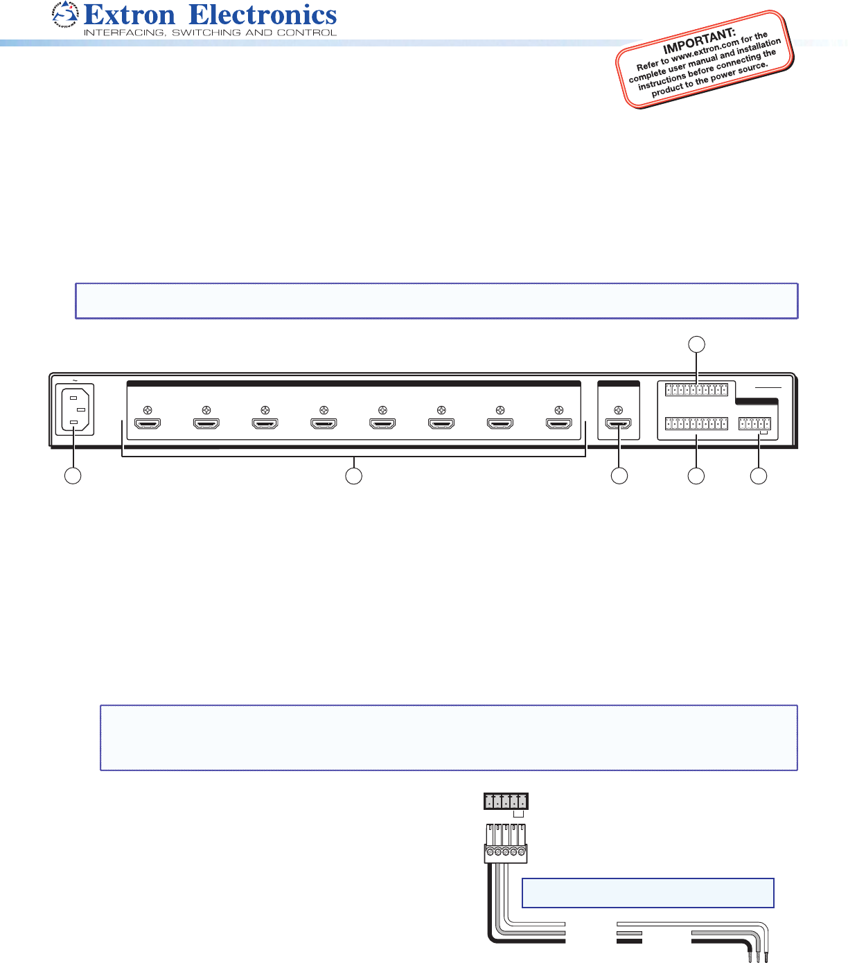
Rear Panel Features and Connections
NOTE: Figure 1 shows an SW8 HDMI, which has eight input connectors. The rear panel of the SW6 HDMI is identical except
for the number of input connectors (six).
SW8 HDMI
1
TALLY OUT
CONTACT
RS-232 AUTO
1234+V 5678+V
1234G567 8G
Tx Rx G
50-60Hz
100-240V 0.3A MAX
2 3 4 5 6 7 8
REMOTE
OUTPUT
INPUTS
1
2
3
6
4
5
Figure 1. SW8 HDMI Rear Panel
a
Female IEC power connector
b
HDMI input connectors
c
HDMI output connector
d
Contact closure port
e
RS-232 and auto-input switching connector
f
Tally Out port
Installation Steps
1. Turn off all of the equipment and disconnect it from the power source.
2. Mount the switcher on a rack shelf or furniture (optional. See the SW HDMI Series User Guide for the procedure).
3. Connect HDMI input sources to one or more of the SW HDMI input connectors (
b
on the rear panel diagram in gure 1).
NOTE: LockIt
®
cable lacing brackets, one for each HDMI input and output connector, are provided with the SW HDMI.
These brackets can be used to secure the HDMI cables to the rear panel connectors to reduce stress on the HDMI
connectors and prevent signal loss due to loose cable connections. For information on attaching the LockIt brackets,
see the SW HDMI Series User Guide, available at www.extron.com.
4. Connect an HDMI output device to the output connector (
c
).
By default, the EDID of this device is stored at the HDMI inputs.
5. Connect control devices: Connect your computer to one of the
following SW HDMI communication ports to congure and control
the switcher via SIS commands:
z RS-232 port — Connect the unterminated transmit, receive,
and ground wires of the RS-232 cable to the rst three pins
on the provided 5-pole captive screw plug, as shown in the
illustration at right. Connect the plug to the rear panel Remote
shared connector (
e
in gure 1), and the other end of the
cable to your computer serial port. Protocol for the RS-232
port is 9600 baud, 8 data bits, 1 stop bit, no parity.
z Cong port — USB mini-B connector (
f
on the front panel
diagram on page 3) for USB control.
RS-232 Auto
Computer or
Contr
RS-232 Port
SW HDMI Series Switcher
Rear Panel
Remote Port
NOTE: If you use cable that has a drain
wire, tie the drain wire to ground at both ends.
TxRx
G
Ground (G)
Transmit (Tx)
Receive (Rx)
Transmit (Tx)
Receive (Rx)
Product Category
1


