FS-RA-CLX_SlotServer_Instruction_Manual_(T17011) Page 21 of 34
FieldServer Technologies 1991 Tarob Court Milpitas, California 95035 USA Web:www.fieldServer.com
Tel: (408) 262-2299 Fax: (408) 262-2296 Toll_Free: 888-509-1970 email: support@fieldServer.com
8. Programming the ControlLogix CPU for larger SlotServer Interfaces
The previous example is for accessing only one Data Array. The following steps describe how to
access multiple Data Arrays.
8.1. Multiple Input Data Arrays
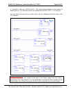
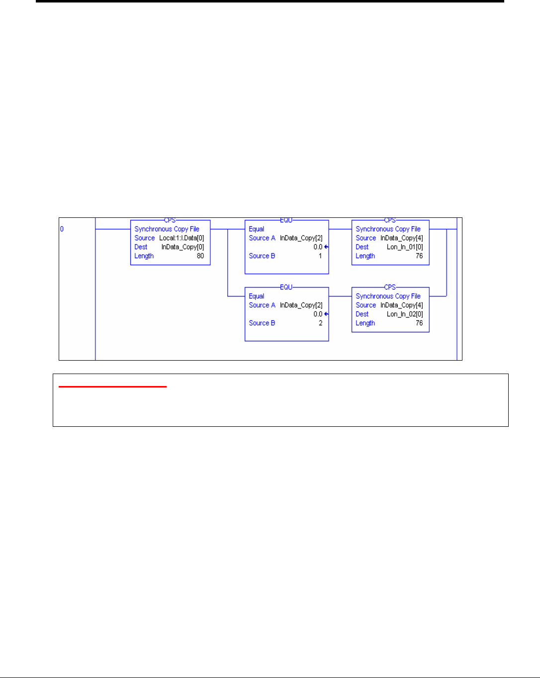
In this example, we access Input Data Arrays In[1] up to In[24]. We simply add to the
existing ladder program as shown in the Quickstart example. Add a branch after the CPS
element that copies the input image Tag and copy and paste EQU and CPS elements from
the first rung. Create a new Input Tag for Lon_In_02 of type REAL and dimension 76.
Finally, remember to set the EQU Source B value to 2 to compare for incoming data from
the 2
nd
LonWorks functional block which is In[1].
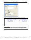
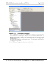
See the ladder program below how to add In[1].
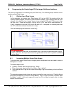
Very Important Note!
It is very important to first make a synchronous copy of the input image data before using it.
If this is not done, the input data cannot be guaranteed to be from a specific LonWorks
Function Block.
8.2. Accessing Multiple Output Data Arrays
To access more output Data Arrays is slightly more complicated since we need to create a
Multiplexer in Ladder.
The basic steps include:
• Create a Counter which counts up every 100ms.
• Place the counter value into the Lon_Out_xx Tag at offset 2.
• Copy and the whole Tag into the output Data Image Tag for transferring to the LonWorks
network.
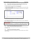
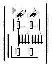
The example program below shows an output counter that can count up to 25 which allows
the transfer of data into 25 Output Function Blocks. Only 2 rungs are shown to transfer data
for blocks 1 and 2. Add more rungs with more Lon_Out_xx tags to transfer data to other
output Function Blocks.


