HYDRA
Service Manual
5-8
5-5. Power Supply Troubleshooting
Warning
To avoid electric shock, disconnect all channelinputs from the
instrument before performing anytroubleshooting operations.
5-6. Raw DC Supply
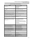
With the instrument connected to line power (120V ac, 60 Hz) and turned ON, check for
approximately 14V dc between A1TP1 (GND) and the "+" terminal of capacitor A1C7
(or the cathode of either A1CR2 or A1CR3). (This voltage is approximately 30V dc at
240V ac line.) If no voltage or a very low voltage is present, check for approximately
24V ac across the secondary of the power transformer (or approximately 50V ac at 240V
ac line.)
The voltage at the output of A1U19 (also A1TP7), should be about +5.2V dc. At 120V
ac, 60-Hz line power input, the line current is approximately 29 mA with the IEEE-488
Option installed or 20 mA without the IEEE-488 Option installed. At 50-Hz, 120V ac
line power input, there is a 5-10% increase in these two current figures.
5-7. Power Fail Detection
The Power Fail Detection circuit monitors the Raw Supply so that the Microprocessor
can be signaled when power is failing. Check for approximately 1.23V dc between the
inverting comparator input (A1U24-2) and GND (A1TP1). If the Raw Supply voltage is
higher than approximately +8.3V dc, comparator output (A1U24-1) should be near VCC.
If the comparator output is near 0V dc during normal operation, the Microprocessor will
sense that power is failing and will not be able to complete a scan operation.
5-8. 5-Volt Switching Supply
Use an oscilloscope to troubleshoot the 5-volt switching supply. With the oscilloscope
common connected to A1TP1, check the waveform at either A1U9, pin 4 or A1T1, pin 2
to determine the loading on the 5-volt switching supply. The output voltage of the 5-volt
switching supply at A1TP2 (VCC) is normally about 5.1V dc with respect to A1TP1
(GND). Note that a fault in the load (high or low resistance) can appear as a faulty output
voltage of the 5-volt switching supply.
• Normal Load:
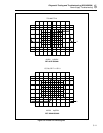
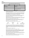
The signal at A1U9-4 (with respect to A1TP1) is a square wave with a period of 9 µs to
11 µs and an ON (voltage is low) duty ratio of about 0.38 with the line voltage at 120V
ac. The amplitude is usually about 15V p-p. The positive-going edge will be "fuzzy" as
the duty ratio is varying to compensate for the ripple of the raw supply and the pulsing
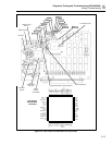
load of the inverter supply. See Figure 5-2A (NORMAL LOAD).
• Very Heavy Load:
Under heavy load (example: A3 A/D Converter PCA has a short circuit) it could load
down the power supply voltage such that the current limiting feature is folding the
supply back. For example, if the supply is folded back due to excessive current draw,
unplug the ribbon cable at A3J10 on the A/D Converter PCA. When tracking down
power supply loads, use a sensitive voltmeter and look for resistive drops across filter
chokes, low value decoupling resistors, and circuit traces. Also check for devices that are
too warm. On the A3 A/D Converter PCA, all devices run cool except A3U5
microprocessor and A3U8 FPGA, which run warm, but not hot.


