HYDRA
Service Manual
5-10
For the inverter to operate, the 110-kHz oscillator must be operating properly. If the
signal at A1U22-3 is missing, begin by checking the voltage at A1TP7. The voltage
should be about 5.1V dc. Then, using an oscilloscope, check for a square wave signal at
A1U23-9 and a square wave signal at A1U23-8. If the FETs are getting proper drive
signals, failures that heavily load the inverter supply will usually cause the inverter to
draw enough current to make the switcher supply go into current limit. Shorted rectifier
diodes and shorted electrolytic capacitors will cause heavy load conditions for the
inverter.
Note
When making voltage measurements in the invertercircuit, remember that
there are two separategrounds. The outguard ground is the ’GND’ testpoint
(A1TP1), and the inguard ground is the’COM’ test point (A1TP30).
The inguard regulator circuits for VDD and VSS have current limits. Shorts and heavy
loads between VDD and COM, VSS and COM, and VDD and VSS will cause one or
both supplies to go into current limit. The current supplied by either supply can be
checked by measuring the voltage across the current sense resistors, A1R13 and A1R15.
The typical voltage across A1R13 is 0.30 and the typical voltage across A1R15 is 0.40V.
Generally, open electrolytic capacitors in the inverter supply will cause excessive ripple
for the affected supply. Also, the rectified dc voltage for the supply with the open
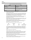
capacitor will be lower than normal. Normal voltage levels at the rectifier outputs for
each inverter supply are shown in Table 5-2.
The loads for the inguard supplies can be disconnected by removing the cable to the A/D
Converter PCA at A3J10. The inguard regulator circuits and VDDR regulator will
operate with no loads, and troubleshooting can be performed by making voltage
measurements.
The normal input current to the inverter supply is about 11.25 mA, or 0.225 mV across
A1R38 (when the instrument is not measuring).
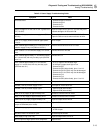
Table 5-3 provides a Power Supply troubleshooting guide.


