HYDRA
Service Manual
5-24
REVIEW
REM SCAN
x1 k
EXT
SET
FUNC
mV
TR
1
Ω
s41f.eps
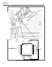
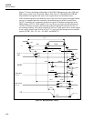
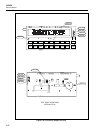
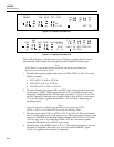
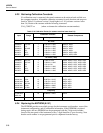
Figure 5-10. Display Test Pattern #1
LAST
MAX
MIN AUTO MON
M
LIMIT
HI
LO
OFF
CAL
PRN
Mx+B
ALARM
°C °F RO
AC DC
Hz
CH
2
F
s42f.eps
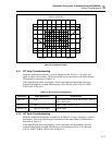
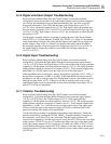
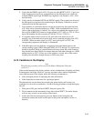
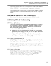
Figure 5-11. Display Test Pattern #2
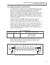
When a Hydra display is initially powered up, all display segments should come on
automatically. If this display does not appear, proceed with the following steps:
Note
If the display is operational but has problems whenfront-panel buttons are
pressed, proceed directlyto step 9.
1. Check the three power supplies with respect to GND (A2TP3 or A2U1-42) on the
Display Assembly.
• VCC (A2U1-21) 4.85 to 5.35V dc
• VEE (A2U1-4)-4.75 to -5.25V dc
• VLOAD (A2U1-5)-28.5 to -32.0V dc
2. Check the filament drive signals FIL1 and FIL2; these connect to the last two pins
on each end of A2DS1. These signals should be 5.4V ac with FIL2 biased to be
about 6.8V dc higher than the VLOAD supply (nominally a -23.2V dc level). FIL1
and FIL2 should be 180 degrees out of phase. If the dc bias of FIL2 is not at about -
23.2V dc, the display segments that should be "off" will show a shadowing (or
speckling) effect.
Note
It may be necessary to disable the watchdog resetby jumpering A2TP1
(A2U5-3, A2U5-11) to GND (A2TP3) toverify the following items.
3. Check the clock signal CLK1 at A2TP2, A2U1-2, and A2U4-3. This signal should
be a 614.4-kHz square wave (1.628 ms per cycle). This signal depends on an E clock
signal of 1.2288 MHz from the Hydra Main Assembly. If the E clock is 819.2 kHz
(1.221 ms per cycle), it is possible that SWR2 (A2J1-16) is shorted to ground,
causing the Microprocessor to HALT at power-up.
4. Check the state of the RESET signal (A2U1-1). This signal should be low once the
reset time is completed (after power-up). Also verify that the RESET* signal
(A2U6-3) is high after the reset time is completed.


