5700A/5720A Series II Calibrator
Service Manual
2-136
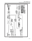
In this circuit, WB MUXA, WB MUXB, and WB MUXC are decoded by U8 to generate
four control lines, These are inverted and level-shifted by comparators in U10 and U11.
The output of these comparators create 16-32 MHz FILTER, 8-16 MHz FILTER, 4-8
MHz FILTER, 2-4 MHz FILTER, 1-2 MHz FILTER, and Q8/Q9 SELECT, which are
used in the filter switch drive circuitry.
Control line WB FBS is inverted and level-shifted by a comparator in U10. This creates
FILTER BAND SWITCH, which is also used in the filter selection circuitry. Control
line WB ON/OFF* shuts down the 8 MHz clock generator and vco when the wideband
module is not in use.
2-219. Phase-Locked Loop and Divider Circuit
The phase-locked loop and divider circuit uses 8 MHz clock generator U15, synthesizer
IC U1, amplifier U2, vco U3, and dividers in U4 and U5 to generate an ECL-level square
wave from 1.1 MHz to 30 MHz.
The 8 MHz clock generator creates the 8 MHz reference frequency from the 8 MHz
system clock lines CLK and CLK*, which is a low level (~200 mV p-p) 8 MHz sine
wave generated on the Regulator/Guard Crossing (A17) assembly. Comparator U15
converts this sine wave into a TTL-level 8 MHz square wave to provide the reference
frequency for synthesizer IC U1.
Synthesizer IC U1 contains two programmable divide-by-N counters and a phase
detector. The divide-by-N counters are controlled by inputs from the guarded digital bus,
which are latched into internal latches on the IC. NOR gates in U14 are used to gate the
chip select (CS14) and write (WR) lines from the digital bus. This forms the strobe pulse
necessary to latch the frequency data into the synthesizer IC.
The first divide-by-N counter is programmed to divide the 8 MHz reference by 160 to
give 50 kHz. This, in turn, is applied to one input of the internal phase detector. The
other divide-by-N counter is used to divide the feedback frequency at pin 3 by 80 to 160
in 1 digit steps, and then apply it to the second input of the phase detector. The loop is
locked when the two inputs to the phase detector are the same frequency and phase.
With a 50 kHz reference frequency and the feedback divider programmed between 80
and 160, the input frequency at pin 3 (feedback frequency) must be between 4 MHz and
8 MHz. (50 kHz x 80 = 4 MHz and 50 kHz x 160 = 8 MHz.)
The frequency into U1 pin 3 is generated by the vco (U3) and dividers in U4 and U5. A
flip flop in U4 divides the vco frequency by 2 and the binary counter in U5 further
divides by 4 to give a total division of 8.
If the input to U1 pin 3 is between 4 MHz and 8 MHz, then the vco frequency before the
divide-by-8 must be 32 MHz to 64 MHz.
The phase detector outputs ("0V" on pin 14 and "0R" on pin 15) of the synthesizer U1
are used by the amplifier (U2) to control the vco (U3). If the divider feedback frequency
is greater than the 50 kHz reference frequency, or if the phase of the divider feedback
frequency leads the output, then 0V pulses low while output 0R remains high.
If the divider feedback frequency is less than the 50 kHz reference frequency, of if the
phase of the divider feedback frequency lags the output, then 0R pulses low and the
output 0V remains high.
When the feedback frequency and the 50 kHz reference frequency are the same and in
phase, the output 0V and 0R both remain high except for a small period when both pulse
low in phase. This condition occurs when the loop is locked.


