Maintenance
Installing a Wideband AC Module (Option -03)
4
4-11
4-19. Installing a Wideband AC Module (Option -03)
CAUTION
The Wideband option circuit board assemblies contain static-
sensitive components. Use caution to avoid static discharge
when handling the modules.
The procedure that follows can be used to install a 5700A-03 Wideband AC Voltage
module in a Calibrator. The option consists of two circuit board assemblies. This
procedure is to be done only at Service Centers.
1. Remove the top and bottom covers and analog section cover. (See ACCESS
PROCEDURES this section)
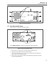
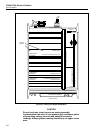
2. Referring to Figure 4-5, locate the slots for the Wideband Output Module (A5) and
the Wideband Oscillator Module (A6).
3. Make sure the cable supplied with the Wideband option is connected between the
Wideband Output and Wideband Oscillator assemblies.
4. Uncoil the internal wideband output cable one turn from the Calibrator chassis and
connect it to the coaxial connector on the Wideband Output Module. Make sure the
cable is routed in such a way as to avoid shorting to ground when the board is
installed in the chassis.
5. Install the Wideband Output and Wideband Oscillator Modules and lock the nylon
ears.
6. Run the Wideband Gains Calibration procedure as described in Section 3.
7. Perform the Wideband Flatness Calibration procedure as described in Section 3. The
Wideband option is now installed and ready for use.
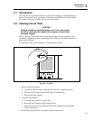
4-20. Clearing Ghost Images from the Control Display
After prolonged periods of displaying the same message on the Control Display, you
may notice a non-uniform brightness of pixels across the display. This phenomenon can
be cleared up by lighting up the whole display and leaving it on overnight (or at least
several hours). Proceed as follows to burn in the Control Display:
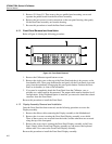
1. Turn on the Calibrator and press the "Setup Menus" softkey.
2. Press the "Self Test & Diags" softkey.
3. Press the "5700 Self Diags" softkey.
4. Press the "Front Panel Tests" softkey.
5. Under the "Display" label, press the "Control" softkey.
6. Press the "All On" softkey. This causes all Control Display pixels to light. Press the
RESET key or press PREV MENU six times to return to normal operation after an
overnight or equivalent burn in period.
4-21. Replacing the Clock/Calendar Backup Battery
To replace the lithium button-type battery on the CPU Assembly (A20), proceed as
follows:
1. Make sure the power is off and the line power cord disconnected.


