Troubleshooting
Component-level Troubleshooting
5
5-57
less than 4 µV. If a failure is detected check U7, U8, and associated components.
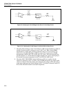
Using a DMM measure the dc voltage across the 500Ω resistor in Z2 by connecting
the DMM HI to TP18 and the DMM LO to TP17. Note this voltage which should be
around 5.0V. Next, measure the voltage across the 1 kΩ resistor in Z2 by connecting
the DMM HI to TP16 and the DMM LO to TP6. The voltage should be double and
opposite polarity (gain = -2)of that previously measured (about -10V). If a failure is
detected check U9, U10, and associated components.
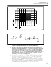
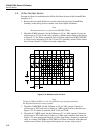
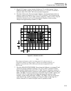
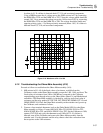
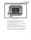
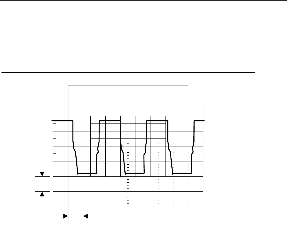
1 V
10 ms
F5-16.EPS
Figure 5-16. Waveform at Pin 13 of U6
5-12. Troubleshooting the Ohms Main Assembly (A10)
Proceed as follows to troubleshoot the Ohms Main assembly (A10):
1. MΩ resistor in R1. All of the fixed values of resistance, available from the
Calibrator, reside on the Ohms Main assembly except the 1.9Ω, 1.0Ω, and short. The
fixed values of resistance from 10Ω to 100 MΩ are connected to the Calibrator
output binding posts through relays on the Ohms Main, Ohms Cal, and Motherboard
assemblies. The Ohms Main assembly is checked by verifying each fixed value of
resistance and the relay path to INT OUT HI, INT SENSE HI, OHMS OUT LO, and
OHMS SENSE LO. Place the Ohms Main assembly on the extender card, power up
the Calibrator, and continue as follows.
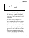
2. Connect a four-terminal ohmmeter (such as the Fluke Model 8505A) to the Ohms
Main assembly as follows. Connect 8505A IN HI to TP4, 8505A IN LO to TP3,
8505A SENSE HI to TP5, and 8505A SENSE LO to TP2. Set the Calibrator to 10Ω,
operate, EXT SNS and verify the ohmmeter reads 10Ω ±0.07%. If a failure is
detected, turn off the Calibrator and remove the Ohms Main assembly from the
extender card. Use the schematic and the relay chart to check the connection from
the test points to the 10Ω resistance.


