Theory of Operation
System Interconnect Detailed Circuit Description
2
2-17
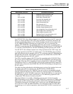
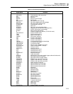
Table 2-1. Analog Motherboard Connectors
Motherboard Connector Connected to Assembly
J101 Wideband Oscillator Assembly (A6)
J111 Wideband Output Assembly (A5)
J201 and J202 Switch Matrix Assembly (A8)
J211 and J212 Current/Hi-Res Assembly (A7)
J301 and J302 Ohms Main Assembly (A10)
J311 and J312 Ohms Cal Assembly (A9)
J401 and J402 DAC Assembly (A11)
J501 and J502 Oscillator Control Assembly (A12)
J511 and J512 Oscillator Output Assembly (A13)
J601 and J602 High Voltage/High Current Assembly (A15)
J611 and J612 High Voltage Control Assembly (A14)
J701 and J702 Power Amplifier Assembly (A16)
J801 and J802 Regulator/Guard Crossing Assembly (A17)
J901 and J902 Filter/PA Supply Assembly (A18)
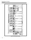
Line INT OUT HI is the calibrator output for ac voltage operation in the 22V range and
below, dc voltage operation in the 220V range and below, all resistance functions, and
all ac/dc current ranges. Relays on the Current assembly route the current output to the
AUX CURRENT OUTPUT binding post via the I OUT line if so selected by the
operator. INT SENSE HI is the sense high path during these modes of operation. INT
OUT HI is connected to the OUTPUT HI binding post through relay K1. INT SENSE HI
is connected to the SENSE HI or OUTPUT HI binding post through relays K2 and K3.
Line HV OUT is the calibrator output for dc voltage operation in the 1100V range, and
ac voltage operation in the 220V and 1100V ranges. Line HV SENSE is the sense high
path during these modes of operation. HV OUT is connected to the OUT HI binding post
through relays K9 and K1. HV SENSE is connected to the SENSE HI or OUTPUT HI
binding post through relays K10, K2, and K3.
The 5725A Amplifier output is B OUT HI and the sense high path is B SNS HI. When
the 5725A is active, B OUT HI is connected to the OUT HI binding post through relays
K4 and K1. When the 5725A Amplifier is inactive, B OUT HI is connected to GUARD
CHASSIS by relay K12. Line B SNS HI is tied to B OUT HI through diode clamps CR1
and CR2 and is connected to the SENSE HI or OUTPUT HI binding post through relays
K5, K2, and K3.
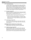
The cable from the motherboard to the binding posts consists of six insulated wires and
six shields, each with its own drain wire. The OUT HI line, SENSE HI line,
OUT/SENSE HI line and AUX CURRENT line each connect to an insulated wire and
each has a shield around the wire. These shields are connected to OUT LO, SENSE LO,
OUT/SENSE LO, and I/V GUARD, respectively. The I/V GUARD line is connected to I
GUARD during operation in the current mode or V GUARD during operation in the
voltage mode. This selection is done by relay K11.
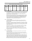
When the Calibrator is in standby, all binding posts are open-circuited except the
GROUND binding post. In addition, GUARD CHASSIS is connected to S COM by K6.
When in the operate condition, this connection is broken (K6 energized) and GUARD
CHASSIS is connected to V GUARD via K7, which goes to the GUARD binding post,
and to OUT LO via K8. GUARD CHASSIS is also connected to OSC LO GD by K13
except during ac or dc millivolt operation, when instead OSC LO GD is connected to S
COM.


