Making Measurements
21
Testing Diodes
Caution
To avoid possible damage to the meter or to
the equipment under test, disconnect circuit
power and discharge all high-voltage
capacitors before testing diodes.
Use the diode test to check diodes, transistors, silicon
controlled rectifiers (SCRs), and other semiconductor
devices. This function tests a semiconductor junction by
sending a current through the junction, then measuring
the junction’s voltage drop. A good silicon junction drops
between 0.5 V and 0.8 V.
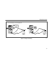
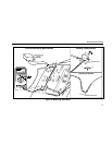
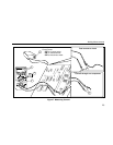
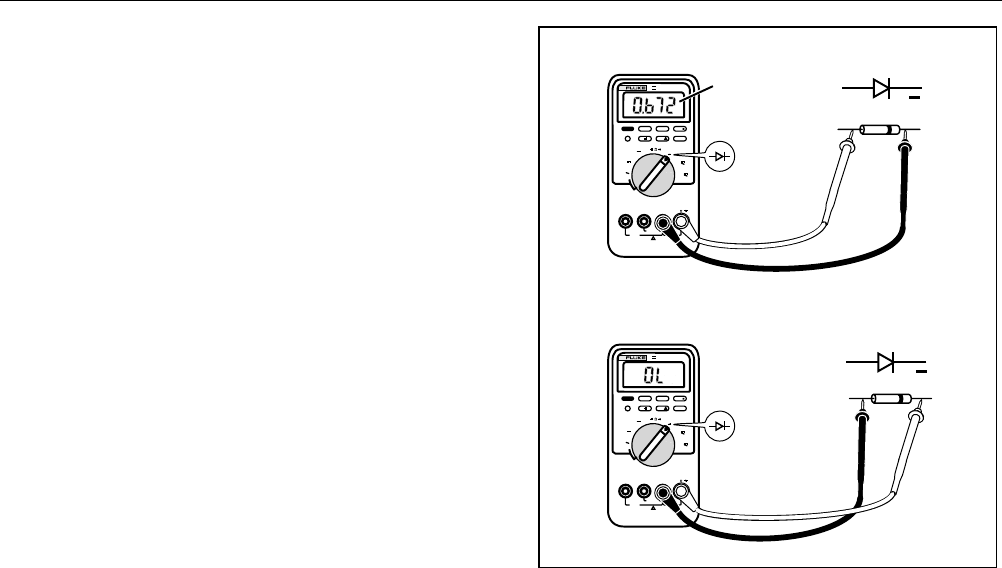
To test a diode out of a circuit, set up the meter as shown
in Figure 6. For forward-bias readings on any
semiconductor component, place the red test lead on the
component’s positive terminal and place the black lead
on the component’s negative terminal.
In a circuit, a good diode should still produce a forward-
bias reading of 0.5 V to 0.8 V; however, the reverse-bias
reading can vary depending on the resistance of other
pathways between the probe tips.
MIN MAX RANGE HOLD
H
HzREL
mA
A
mV
V
V
OFF
!
!
A
COM
V
mA µA
1000V MAX
400mA MAX
FUSED
10A MAX
FUSED
PEAK MIN MAX
µA
CAT II
+
Typical
Reading
MIN MAX RANGE HOLD
H
HzREL
mA
A
mV
V
V
OFF
!
!
A
COM
V
mA µA
1000V MAX
400mA MAX
FUSED
10A MAX
FUSED
PEAK MIN MAX
µA
CAT II
+
Forward Bias
Reverse Bias
4 1/2 DIGITS
1 Seconds
87
TRUE RMS MULTIMETER
III
4 1/2 DIGITS
1 Seconds
87
TRUE RMS MULTIMETER
III
iy9f.eps
Figure 6. Testing a Diode


