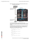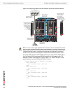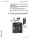
FortiGate-5140 fabric backplane communication Example active-passive redundant link configuration
FortiSwitch-5003A and 5003 Fabric and Base Backplane Communications Guide
01-30000-85717-20081205 37
The configuration of the spanning tree instances determines whether you create
an active-passive or active-active configuration:
• For an active-passive configuration, you can create one spanning tree
instance on all three devices and give one of the FortiSwitch-5003A boards a
higher priority. This board becomes the active board in the configuration
because spanning tree sends all traffic to the high priority spanning tree
instance. If the active board fails, spanning tree re-directs all traffic to the other
board.
• For an active-active configuration, you create two or more spanning tree
instances on all three devices and give some instances a higher priority on one
FortiSwitch-5003A board and give other instances a higher on the other
FortiSwitch-5003A board. While both FortiSwitch-5003A boards are, the
spanning tree configuration distributes traffic to both boards. If one of the
FortiSwitch-5003A boards fails, spanning tree redirects all of the traffic to the
board that is still operating.
In both active-passive or active-active configurations, if one of the
FortiSwitch-5003A boards fails, sessions are temporarily interrupted because the
FortiSwitch-5003A boards do not store session information.
Example active-passive redundant link configuration
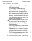
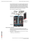
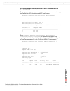
Figure 15 shows an example redundant link aggregation configuration. In this
configuration an external switch is connected to two FortiSwitch-5003A front panel
F7 interfaces. The switch adds VLAN tags to traffic from two internal and two
external networks. Packets from each network get different VLAN tags. Packets
from internal networks are tagged as 103 and 104 and packets from the external
networks are tagged as 105 and 106.
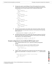
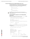
To make this an active-passive configuration, the spanning tree instances on the
FortiSwitch-5003A board in slot 1 should have a higher priority than the spanning
tree instances on the FortiSwitch-5003A board in slot 2. The FortiSwitch-5003A
board in slot 1 becomes the root for both spanning tree instances. Because of the
priority settings, MSTP sends all packets to the FortiSwitch-5003A board in slot 1.
If this board fails, MSTP re-directs all packets to the FortiSwitch-5003A board in
slot 2.
For a given spanning tree instance, MSTP directs packets to the device with the
lowest priority value. To give a spanning tree instance a higher priority on a device
you must configure the instance on that device with a lower priority value. The
lower priority value gives the device a higher spanning tree priority for a given
spanning tree instance.
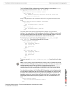
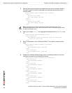
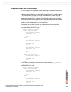
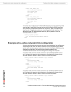
In this example the spanning tree priority values on the FortiSwitch-5003A board
in slot 1 are both set to 4096 and the spanning tree priority values on the
FortiSwitch-5003A board in slot 2 are both set to 40960. So spanning tree directs
all traffic to the FortiSwitch-5003A board in slot 1.
Note: If you have more than one spanning tree instance you can still configure an
active-passive configuration by setting the priorities of all spanning tree instances to be
higher for the same FortiSwitch-5003A board.


