


© Copyright 2008 Fortinet Incorporated. All rights reserved.
Products mentioned in this document are trademarks or registered trade-
marks of their respective holders.
Regulatory Compliance
FCC Class A Part 15 CSA/CUS
15 December 2008
QuickStart Guide
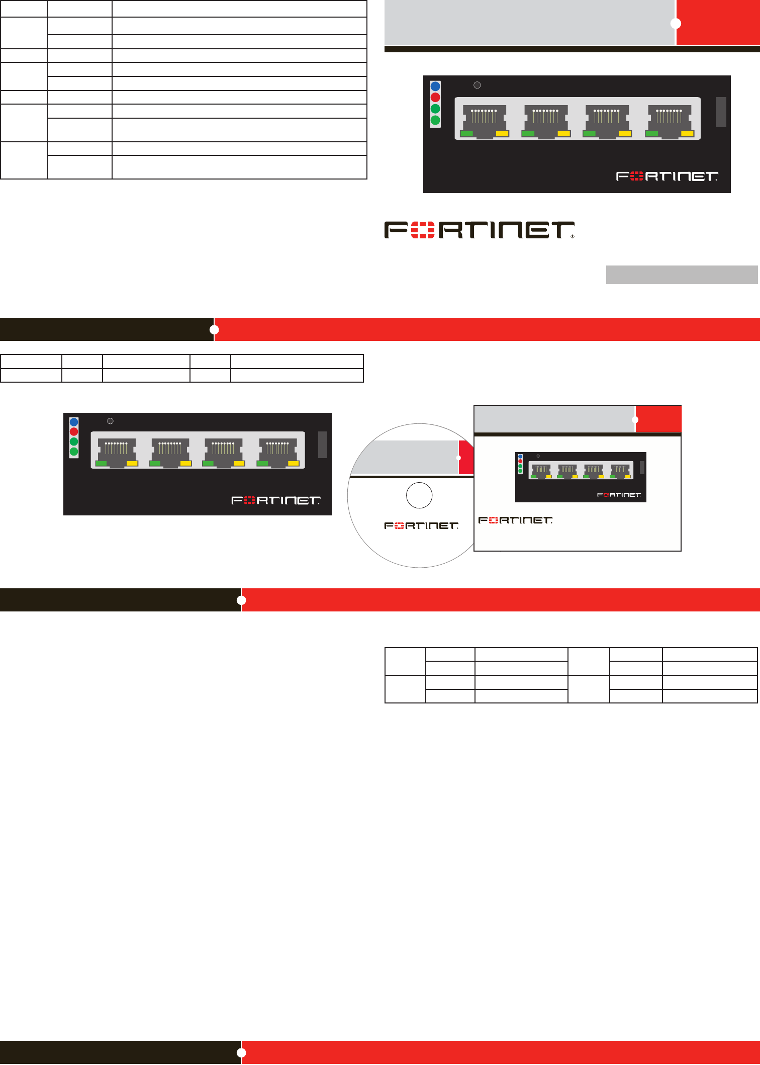
Package Contents
Installing the AMC Module
Conguring
ASM -C E 4
1 2 3 4
HS
OOS
PWR
OT
RST
Tools and Documenation
FortiGate-30B
Copyright 2008 Fortinet Incorporated. All rights reserved.
Trademarks
QuickStart Guide
ASM- CE 4
1 2 3 4
HS
OOS
PWR
OT
RST
ASM-CE4
1 2 3 4
HS
OOS
PWR
OT
RST
It is important to carefully seat the FortiGate ASM CE4 module all the way into the chassis.
Only then will the FortiGate ASM CE4 module power-on.
To complete this procedure, you need:
• A FortiGate ASM CE4 module
• A FortiGate chassis with an empty AMC single-width (SW) opening.
• To avoid any electrostatic discharge, install in a static free area.
FortiGate ASM CE4 modules are not hot swappable. The procedure for inserting the
FortiGate ASM CE4 module into a FortiGate chassis slot requires the FortiGate unit to be
powered off.
To avoid any electrostatic discharge (ESD) when handling FortiGate ASM CE4 modules,
install in a static free area.
To insert a FortiGate ASM CE4 module into a FortiGate chassis
Ensure the FortiGate unit is powered off before proceeding.1.
Remove the panel block on the FortiGate unit using the hot swap latch.2.
Pull the latch on the ASM CE4 module to the extended position.3.
Insert the FortiGate ASM CE4 module into the empty slot in the chassis. Ensure the 4.
Fortinet logo is right-side up. It should be on the upper-right corner of the module.
Carefully guide the module into the chassis.5.
Insert the module by applying moderate force to the front faceplate near the upper edge 6.
to slide the module into the slot.
The module should glide smoothly into the chassis. If you encounter any resistance
while sliding the module in, the module could be aligned incorrectly. Pull the module
back out and try inserting it again.
Press the hot swap latch to lock in the module.7.
Power on the FortiGate unit. 8. The hot swap (HS) LED turns on and then begins ashing.
01-30000-86935-20081215
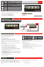
Connector Type Speed Protocol Description
Ports 1 to 4 RJ-45 10/100/1000 Base-T Ethernet Copper network connections.
ASM CE4 module ports
SWx/1 IP: ____.____.____.____ SWx/3 IP: ____.____.____.____
Netmask: ____.____.____.____ Netmask: ____.____.____.____
SWx/2 IP: ____.____.____.____ SWx/4 IP: ____.____.____.____
Netmask: ____.____.____.____ Netmask: ____.____.____.____
Removing the AMC module
Should you need to remove the ASM CE4, shut down the FortiGate unit using proper shut
down procedures.
To remove the ASM CE4 module
Ensure the FortiGate unit is powered off before proceeding.1.
To avoid any electrostatic discharge (ESD) when handling FortiGate ASM CE4 modules, 2.
install in a static free area.
Pull the hot swap latch on the right-hand side of the module to the extended position to 3.
unlock the module from the FortiGate unit.
Gently pull the hot swap latch to remove the module.4.
FortiGate ASM-CE4
LED State Description
HS
Blue Ejection latch open. The module is ready for removal.
Flashing Ejection latch opened during system operation.
OOS LED currently not in use.
PWR
Green The module is properly inserted in the FortiGate unit.
Off The module is not receiving power from the FortiGate unit.
OT LED currently not in use.
Port 1 to 4
Left LED
Green The correct cable is in use and the connected equipment has power.
Flashing Green Network trafc at 100 Mbps. Flashing with the right LED, connection
at 1000 Mbps.
Port 1 to 4
Right LED
Amber The correct cable is in use and the connected equipment has power.
Off Network trafc at 10 Mbps. Flashing with the left LED, connection at
1000 Mbps.
Visit these links for more information and documentation for your Fortinet product.
Technical Documentation - • http://docs.forticare.com
Fortinet Knowledge Center - • http://kc.forticare.com
Fortinet Technical Support - • http://support.fortinet.com
Congure the ports on the ASM-CE4 as you would any other ports on the FortiGate unit. For
more information on conguring ports, see the FortiGate Administration Guide.
Using the web-based manager, go to System > Network > Interface to congure the IP
address and netmask of the ports. The module ports are indicated as SWx/n, where n is the
port number.
Using the Command Line Interface (CLI) use the following commands:
cong system interface
edit <port_number>
set ip <ip_address>
set netmask <netmask>
set allowaccess {http | https | ssh | telnet | ping}
end