


© Copyright 2008 Fortinet Incorporated. All rights reserved.
Products mentioned in this document are trademarks or registered trademarks
of their respective holders.
Regulatory Compliance
FCC Class B Part 15 CSA/CUS
14 October 2008
Visit these links for more information and documentation for your Fortinet product.
Technical Documentation - • http://docs.forticare.com
Fortinet Knowledge Center - • http://kc.forticare.com
Fortinet Technical Support - • http://support.fortinet.com
Connecting
Straight-through
Ethernet cable
AC Power Cable
RJ-45 to
DB-9 Serial Cable
Tools and Documenation
Copyright 2008 Fortinet Incorporated. All rights reserved.
Trademarks
Products mentioned in this document are trademarks.
QuickStart Guide
Welcome | Bienvenue | Willkommen | | Bien venido | Benvenuto
FortiGate-310B-LENC
Rack-Mount
Brackets
310B
CONSOLE
USB
1/2 3/4 5/6 7/8 9/10
POWER
ASM
STATUS
ALARM
HA
NP2 Powered
310B
-LENC
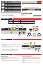
Ethernet cables connect to
computers on the internal network
and to the Internet (public switch
or router)
Power cable
connects to
power supply
Redundant DC
power supply
RJ-45 to DB-9 serial cable
connects to management
computer
CONSOLE
USB
1/2 3/4 5/6
7/8 9/10
POWER
ASM
STATUS
ALARM
HA
NP2 Powered
310B
-LENC
CONSOLE
USB
1/2 3/4 5/6
7/8 9/10
POWER
ASM
STATUS
ALARM
HA
NP2 Powered
Power LED
Status LEDs
USB
10 port
switch
RJ-45 serial
connection
AMC
single-width
module slot
AC power
connection
Redundant
DC power
connection
310B
-LENC
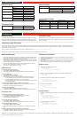
Package Contents
Connector Type Speed Protocol Description
Internal RJ-45 10/100/1000 Base-T Ethernet 10-port switch connection to up to ten devices or the internal network.
CONSOLE RJ-45 9600 bps
8/N/1
RS-232
serial
Optional connection to the management computer.
Provides access to the command line interface.
USB USB USB OptionalconnectionforUSBkeyforrmwarebackupandinstallation.
Connect the following to the FortiGate unit. Ensure the FortiGate unit is placed on a stable
surface.
Insert a network cable to port 1. Insert the other end to the router connected to the Inter-•
net, or to the modem.
Connect a network cable to the Internal port. Insert the other end to a computer or •
switch.
Connect the AC Power Cord to the Power Supply. •
Connect the redundant DC Power Supply to the FortiGate unit if applicable. •
Connect the Power Cord to a surge protected power bar or power supply.•
FortiGate-310B-LENC
01-30006-0475-20081014
LED State Description
Power
Green The FortiGate unit is on.
Off The FortiGate unit is off.
Status
Green Flashes during startup
Off The FortiGate unit is running normally.
HA
Green The FortiGate unit is running in HA mode.
Off The FortiGate unit is not in HA mode.
Alarm
Amber TBD
Off The FortiGate unit is running normally.
Left LED
Ports 1 to 10
Green The correct cable is in use and the connected equipment has power.
Off No network cable connected.
Right LED
Ports 1 to 10
Green Network speed of 1000 megabyte.
Yellow Network speed of 100 megabyte.
Off Network speed of 10 megabyte.
QuickStart Guide
Web-based manager
The FortiGate web-based manager is an easy to use management tool.
Useittoconguretheadministratorpassword,theinterfaceanddefaultgatewayaddresses,
and the DNS server addresses.
Requirements:
An Ethernet connection between the FortiGate unit and management computer. •
A web browser such as FireFox or Internet Explorer on the management computer.•
Command Line Interface (CLI)
TheCLIisafull-featuredmanagementtool.Useittoconguretheadministratorpassword,
the interface addresses, the default gateway address, and the DNS server addresses. To
congureadvancedsettings,seetheToolsandDocumentationCDincludedwiththe
FortiGate unit.
Requirements:
The RJ-45 to DB9 serial connection between the FortiGate unit and management com-•
puter.
A terminal emulation application (HyperTerminal for Windows) on the management •
computer.
Conguration Tools