76 Fortinet Inc.
Transparent mode configuration examples Transparent mode installation
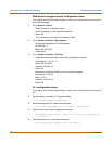
Web-based manager example configuration steps
To configure basic Transparent mode settings and a default route using the
web-based manager
1 Go to System > Status.
• Select Change to Transparent Mode.
• Select Transparent in the Operation Mode list.
•Select OK.
The FortiGate unit changes to Transparent mode.
2 Go to System > Network > Management.
• Change the Management IP and Netmask:
IP: 192.168.1.1
Mask: 255.255.255.0
• Select Apply.
3 Go to System > Network > Routing.
• Select New to add the default route to the external network.
Destination IP: 0.0.0.0
Mask: 0.0.0.0
Gateway: 192.168.1.2
•Select OK.
CLI configuration steps
To configure the Fortinet basic settings and a default route using the CLI:
1 Change the system to operate in Transparent Mode.
set system opmode transparent
2 Add the Management IP address and Netmask.
set system management ip 192.168.1.1 255.255.255.0
3 Add the default route to the external network.
set system route number 1 gw1 192.168.1.2
Example static route to an external destination
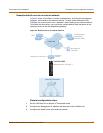
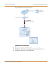
Figure 24 shows a FortiGate unit that requires routes to the FDN located on the
external network. The Fortigate unit does not require routes to the DNS servers or
management computer because they are located on the internal network.
To connect to the FDN, you typically enter a single default route to the external
network. However, for additional security, you can enter static routes to a specific
FortiResponse server in addition to a default route to the external network. If the static
route becomes unavailable (for example, because the IP address of the
FortiResponse server changes) the FortiGate unit can still receive antivirus and NIDS
updates from the FDN using the default route.


