


4.4 Battery charger(BC-6158)
4-12
4.4 Battery charger (BC-6158)
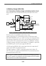
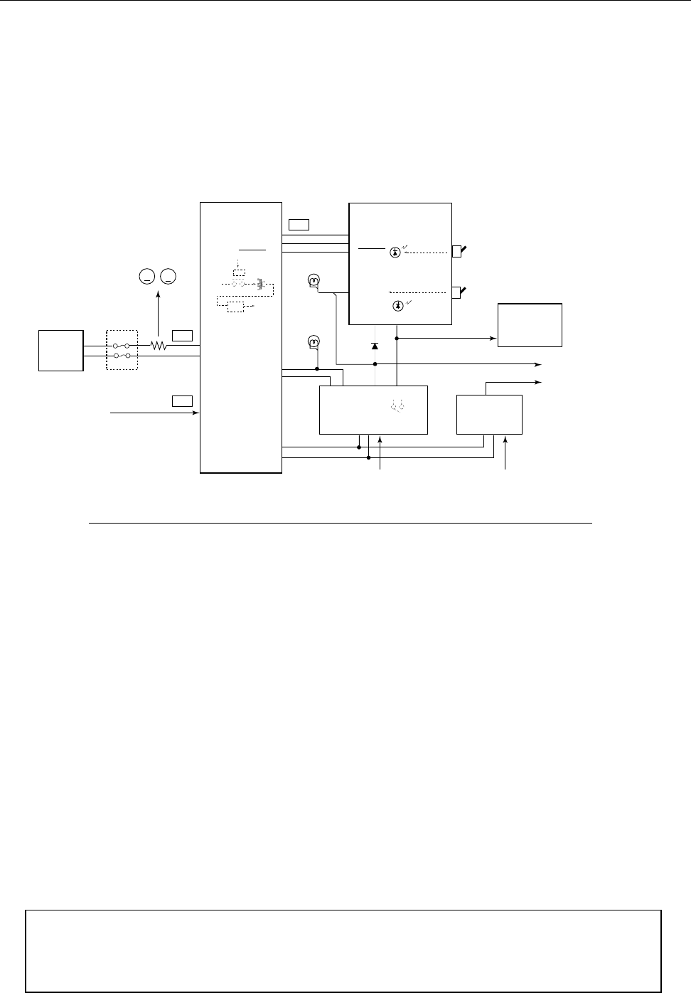
4.4.1 Connection of battery charger and battery monitor circuit
Battery charger BC-6158 is controlled from the battery control panel of the console
panel.
Fig. 4.4.1 Connection of battery charger and battery monitor circuit
The battery monitor circuit (05P0607) monitors battery voltage.
If battery voltage drops to 22 V, [LOW] indicator comes on and the buzzer sounds.
With “BATT CHARGER switch” set to “AUTO”, the charger starts charging the battery
when the battery voltage drops to 24.5 to 25.0 V, and stops charging when the battery is
charged by 28.0 to 28.5 V automatically. If the switch is set to “MANUAL”, the battery
is charged in continuity. The signal to control charging is “3. CHARGE-L” signal which
turns ON/OFF relay K1 on the AC power supply line of BC-6158.
AC FAIL signal from PR-850A (AR), a contact signal of the relay is output when AC
supply is turned “OFF” and switched to the battery.
This signal is supplied to “2. EMG-L” of the battery monitor board to indicate “IN
USE”. This signal is also supplied to FS-5000/2550/1562-25 and automatically reduces
the transmission power to 60 to 70 W.
Note) The “AUTO” position is provided to prevent over discharge of the battery.
This “AUTO” position is not intended to use both the battery and AC/DC supplies
at the same time for so called “floating operation”.
Battery
BC-6158
TB1
1. BATT IN+
2. BATT IN-
TB3
TB2
1. AC(U)
2. AC(V)
AC100/220V
AC100/220V AC100/220V
60A
RC-1800T only
SB-180
1. (+)BATT OUT
2. (-)BATT OUT
PR-850A
PR-850AR
(RC-1800T)
PR-300
1. 24V 2. EMG L
4. BATT+
5. BATT-
6. LAMP 2(NC)
7. LAMP 1
05P0607
3. (+)BATT OUT
4. (-)BATT OUT
5. 24V
6. CHARGE
7. 0V
24V
Back-up
24V Back-up
24V Back-up
24V
Back-up
AC FAIL
AC FAIL
MF/HF SSB
EMG
Lamp
3. CHRG-L
BATT CH. SW
AUTO
OFF
CHARGE
EMG LIGHT
ON
OFF
V
A
24V OUT
Illuumination
Lamp
IN USE
CHARGE
AC iN
K1
REC
T1
Primary system
Duplicate system