


8
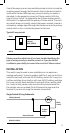
11. OPTIONAL for 3 or 4-way control): Connect the Traveler wire
(usually Red) to the screw terminal marked TRAVELER.
The other end of this Traveler wire connects to the TRAVELER
screw terminal on the 45610 Auxiliary Switch. See the following
section for information about wiring the 45610 Auxiliary Switch.
12. Insert Z-Wave Switch into the switch box being careful not to
pinch or crush wires.
13. Secure the switch to the box using the supplied screws.
14. Mount the wall plate.
15. Reapply power to the circuit at fuse box or circuit breaker
and test the system.
Optional for 3 or 4-Way Control:
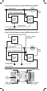
1. The 45610 requires the following 3 wiring connections:
a. The Traveler wire. This is used to send voltage signals to the
primary Z-Wave switch. The signals tell the Z-wave switch
what action to perform.
b. Ground.
c. Neutral.
2. DO NOT connect the 45610 auxiliary switch to the home’s
black Hot (Line) wire.
Observe Important Wiring Information
Important: This switch is rated for and intended to only be used
with copper wire.
The home’s electrical wires may be attached to the screw termi-
nals or inserted into the holes in the back of the switch enclosure
and clamped in place by tightening the screw terminals. Always
follow the recommended wire strip lengths when making wiring
connections.
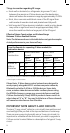
Wire gauge requirements
• Use 14 AWG or larger wires suitable for at least 80° for supply
(HOT), Load, Neutral and Traveler connections.
• Use 12 AWG or larger wires suitable for 80° for ground
connection.
Wire strip length:
• For attachment to screw terminals: Strip insulation 5/8”.
• For attachment using the enclosure’s holes: Strip insulation 5/8”.
You should now be able to use the rocker to manually turn On/Off
the connected load.
Use your primary controller to include the switch in the home
control network after the switch is wired as shown in the above