


4
Things to consider regarding RF range:
• Each wall or obstacle (i.e.: refrigerator, big screen TV, etc.)
between the remote or Z-Wave device and the destination
device will reduce the maximum range by approximately 25-30%.
• Brick, tile or concrete walls block more of the RF signal than
walls made of wooden studs and plasterboard (drywall).
• Wall mounted Z-Wave devices installed in metal junction boxes
may suffer a significant loss of range (approximately 20%)
since the metal box blocks a large part of the RF signal.
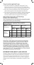
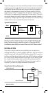
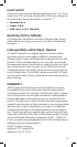
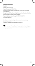
Effects of Home Construction on Wireless Range
Between Z-Wave Enabled Devices
Note: The distances shown in the table below are typical examples.
Actual performance in your home will vary.
From the Remote (or repeating Z-Wave module) to
destination device:
Type of
Construction
Wood Frame with
Drywall
Brick, Tile or
Concrete
Plastic
J-Boxes*
Metal
J-Boxes
Plastic
J-Boxes*
Metal
J-Boxes
Number of
Walls or
Obstacles
0** 100’ 80’ 100’ 80’
1 70’ 56’ 60’ 48’
2 49’ 39’ 36’ 29’
3 34’ 27’ 21’ 17’
* For Plug-in Modules or In-Wall Devices Installed in Plastic Junction Boxes
** Line of Sight / no obstructions
Please Note: Z-Wave home control networks are designed to
work properly alongside 802.11 wireless computer networks,
Bluetooth and other 2.4GHz or 5.8GHz devices. Some baby
cams, wireless video devices and older cordless phones using
the 900MHz frequency range may cause interference and limit
Z-Wave functionality. Many 900MHz products have a switch to
select channel “A” or “B”. You may find that one of these channels
will cause less interference than the other.
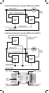
IMPORTANT NOTE ABOUT 3-WAY CIRCUITS
The term “3-way circuit” refers to a circuit with two switches and
one load (light) like you find at the top and bottom of a stairway.
There are many ways to physically wire a 3-way circuit and it is
important to understand how the circuit you wish to upgrade to
Z-Wave control is wired. Below is a description of a typical 3-way
circuit.