


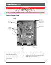


■
GE Zenith Controls 3
■
ZTG/ZTGD Operation and Maintenance Manual (70R-1000D)
Each GE Zenith transfer switch is factory wired and
tested. A complete information package is furnished
with each switch which includes:
a. Sequence of operation.
b. Description and operation of
all accessories supplied.
c. Power panel connection diagram
and schematic.
d. Description and identification of
all customer field connections.
Installation of GE Zenith transfer switches includes:
a. Mounting the transfer switch cabinet.
b. Connection of Source 1, Source 2,
and Load cables or bus bars.
c. Connection of external control
circuits as required.
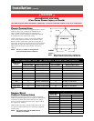
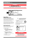
Mounting
Adequate lifting means must be used to mount the
transfer switch into place. The recommended method for
moving the transfer switch using the lifting eyes, where
supplied, and a spreader bar is illustrated in Figure 1.
Enough room should be allowed to open the cabinet
doors fully for inspection and servicing of the switch per
NEC and local codes.
Safety / Installation
DANGER
HAZARDOUS VOLTAGE
(Can Cause Severe Injury or Death)
Turn OFF all power before installation, adjustment, or removal of transfer switch or any of its components.
The safe operation of your switch is GE
Zenith’s focus.
The proper storage, installation, operation and mainte-
nance will help increase the life of the switch.
Equipment Inspection
and Storage
Once you have received the transfer switch, inspect
it for any damage. This includes damage to the
enclosure, power panel, control panel and wiring
harness. If any damage is found or suspected, file a claim
as soon as possible with the carrier and notify the nearest
GE
Zenith representative.
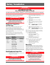
Before installation, if it is necessary, store the transfer
switch in a clean dry place, protected from dirt and
water. Provide ample air circulation and heat, if neces-
sary, to prevent condensation.
5% to 95%
(non-con-
densing)
-30°C to
+75°C
(-22°F to
+167°F)
40-400
AMP
(molded shell)
-20°C to +65°C
(-4°F to +149°F)
40-4000
AMP
(all other frame
and panel types)
-20°C to +60°C
(-4°F to +140°F)
Operating
Storage Temperature
Temperature (Ambient): Humidity
CAUTION
Due to hazardous voltage and current, GE Zenith rec-
ommends that a
GE Zenith Certified technician or a
qualified electrician must perform the
installation and maintenance of the switch.
Final Equipment Inspection
Prior to energizing the transfer switch:
1. Remove any debris incurred, with a vacuum, due
to shipment or installation.
WARNING
Do not use a blower since debris may
become lodged in the electrical and
mechanical components and cause damage.
2. Verify that all cabled connections are
correct and that phase rotation of both sources
match.
3. Check engine start connections.
4. Verify the correct connection of all
control wires.
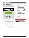
5. Check settings of all timers and adjust
as necessary.
6. Adjust any optional accessories as required.
7. Check the lug torque values of the power
connections.
NOTE
: Lug torque values are specified
in table 2 on pg.4.
8. Make sure that all covers and barriers are
installed and properly fastened.
NOTE
: Power panels ship from GE Zenith
in Source 1 Position.
CAUTION
Before drilling conduit entry holes or any
accessory mounting holes, cover and protect
the switch and control panel to prevent dirt
and metal fragments from entering the
mechanical and electrical components.
Failure to do so may result in
damage and malfunction of the switch.