


■
8 GE Zenith Controls
■
ZTG/ZTGD Operation and Maintenance Manual (70R-1000D)
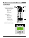
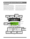
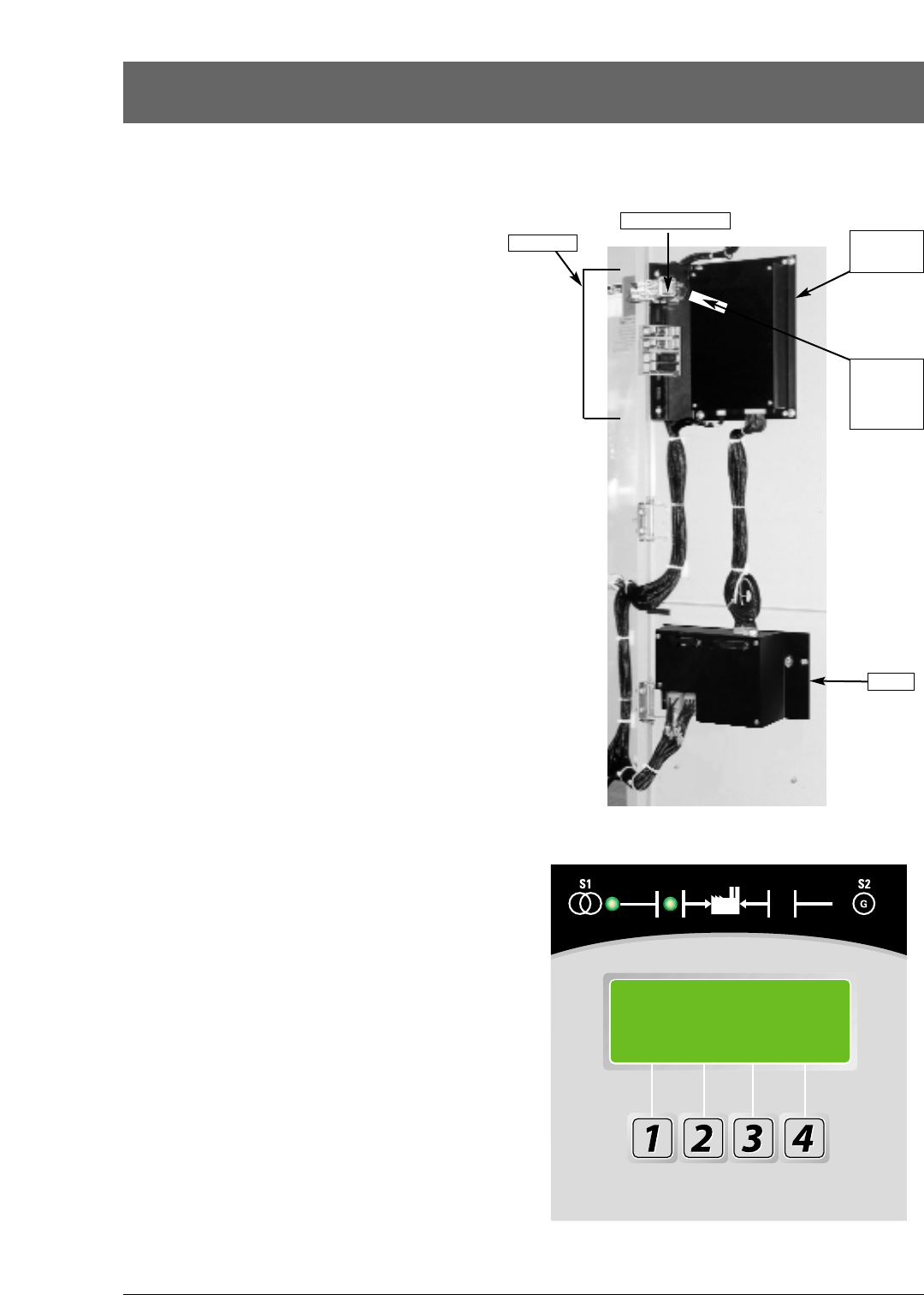
MX150 Microprocessor Controller
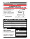
MX150 Controller
Consists of two major assemblies:
I. The Microprocessor contains the following:
A. MX150 Board - Customer Input and Output
(I/O) for system interface. Located on the left
hand side of the back of the unit (see figure 6)
1. I/O accessories that can be found here are:
a. Engine start relay P output
b. Pre-Signal to transfer T3, W3 and
UMD output (optional)
c. Transfer Inhibit Q3 and Q7 input
(optional)
d. Remote test Q2 input (optional)
e. Network interface ZNET
input/output (optional)
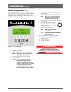
B. LCD and Keypad located on the exterior
of the door (see figure 7)
1. User accessibility to the following:
a. LED indication of source
availability
b. LED indication of transfer
switch position
c. LCD screen indicates:
(1) timer count down (numeric)
(2) event reporting (text)
d. Keypad provides user interface to:
[in conjunction with LCD screen]
(1) Setting sensors and timers
(2) Configuring logic accessories
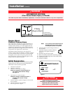
II. The Controls Power Supply (CPS)
Contains transformers which drop line voltage to
control level for controller input and SCR inputs
(see figure 6).
Figure 7
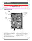
Figure 6
I/O Interface
CPS
Engine Start Relay P
Battery Strip
and
Access
Code Label
MX150
Board
MX150
S1 OK
21:56
MON 23 APR 2002
MORE TEST