


Chapter 2: Installation
14 GE-DS-82 and 82-PoE Ethernet Managed Switch User Manual
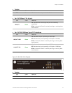
• Per 10/100Base-TX, PoE interfaces (Port-1 to Port-8)
LED Color Function
LNK/ACT Green
Lit: indicates the link through that port is successfully
established
Blink: indicates the Switch is actively sending or receiving data
over that port
PoE In Use Orange
Lit: indicates the port is providing 48VDC in-line power
Off: indicates the connected device is not a PoE Powered
Device (PD)
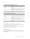
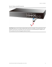
• Per 10/100/1000Base-T port/SFP interfaces
LED Color Function
LNK/ACT 1000 Green
Lit: indicates the port is operating at 1000Mbps
Off: indicates the port is operating at 10Mbps or 100Mbps
Blink: indicates the Switch is actively sending or receiving data
over that port
LNK/ACT 100 Green
Lit: indicates the port is operating at 100Mbps
Off: indicates the port is operating at 10Mbps or 1000Mbps
Blink: indicates the Switch is actively sending or receiving data
over that port
NOTE:
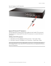
1. Press the RESET button once. The Switch will reboot automatically.
2. Press the RESET button for about 10 seconds. The Switch will revert to the factory
default mode; the entire configuration will be erased.
3. The 2 Gigabit TP/SFP combo ports are shared with port 9/10 of GE-DS-82 / GE-DS-
82-PoE. Both of them can operate at the same time.
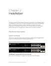
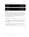
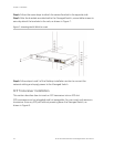
Switch Rear Panel
The rear panel of the Managed Switch includes an AC inlet power socket, which
accepts input power from 100 to 240VAC, 50-60 Hz. Figure 4 shows the rear panel of
the Managed Switch.