


B
B-4
TCP/IP Ethernet Communications User’s Manual - August 1997 GFK-1084B
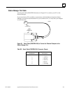
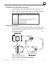
Software Loader Port (Serial Port 2)
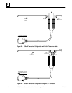
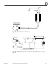
This section presents the information you need to construct a cable for serial
communications between the Ethernet Interface and a PC with the PC Loader software
installed. Information in this section includes serial port settings, pinouts, and cable
diagrams.
An RS-232 to RS-485 converter is required to interface to systems that provide RS-232
compatible interfaces.
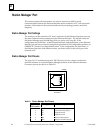
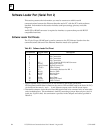
Software Loader Port Pinouts
The 15-pin, D-type, RS-485 port is used to connect to the PC Software Loader when the
communications software in the Ethernet Interface needs to be updated.
Table B-3. Software Loader Port Pinout
Pin Number
Signal Name Description
1
2
3
4
Shield
No Connection
No Connection
No Connection
5
6
7
8
+5V *
RTS (A)
Signal Ground
CTS (B’)
+5V Power for RS-232/485 Converter
Request To Send
Signal Ground, OV
Clear To Send
9
10
11
12
RT *
RD (A’)
RD (B’)
SD (A)
Terminating Resistor for RD **
Receive Data
Receive Data
Send Data
13
14
15
SD (B)
RTS (B)
CTS (A’)
Send Data
Request To Send
Clear To Send
* Signals available at the Connector but are not included in the RS-485 specification.
SD (Send Data) and RD (Receive Data) are the same as TXD and RXD (used in the Series Six PLC).
(A) and (B) are the same as - and + . A and B denote outputs, and A’ and B’ denote inputs.
** Termination resistance for the Receive Data (RD) signal needs to be connected only on units at the
end of multidrop lines. This termination is made by connecting a jumper between pins 9 and 10
inside the 15-pin D-shell; the termination is provided in the adapters and cables specified in
Table B-3.