


TIMERN CN O
COM
NC2
NO2
COM2
LOAD
L1
L2
TIMERN CN O
COM
TO 200/240/277V LINE
TO 120V LINE
NC2
NO2
COM2
H
N
LOAD
TIMERN CN O
COM
TO 24V LINE
NC2
NO2
COM2
H
N
LOAD
N
H
TO 120V LINE
TO LOAD
T
T
T
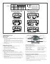
120V Timer, 120V Load and 24V Load
Wired as Single Throw
200/240/277V Timer, 200/240/277V Load, Double Break
Wired as Single Throw
120V Timer, 200/240/277V Load Double Break
Wired as Single Throw
Typical Wiring Diagrams—DPDT
TO POWER SUPPLY
TO POWER SUPPLY 1
TO POWER SUPPLY 2
Timer and Load, Same Voltage
Wired as Single Throw
TO LOAD
TO 120V LINE
H
N
HIGH
LOW
COM
T
LOAD
T
NCTIMERN OCOM
TIMERN CN OC OM
T
TIMERN CN OCOM
120V Two Speed Fan
Wired as Double Throw
Timer and Load, Different Voltage
Wired as Single Throw
Typical Wiring Diagrams—SPDT
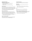
Field Wiring
Timer Internab Wiring
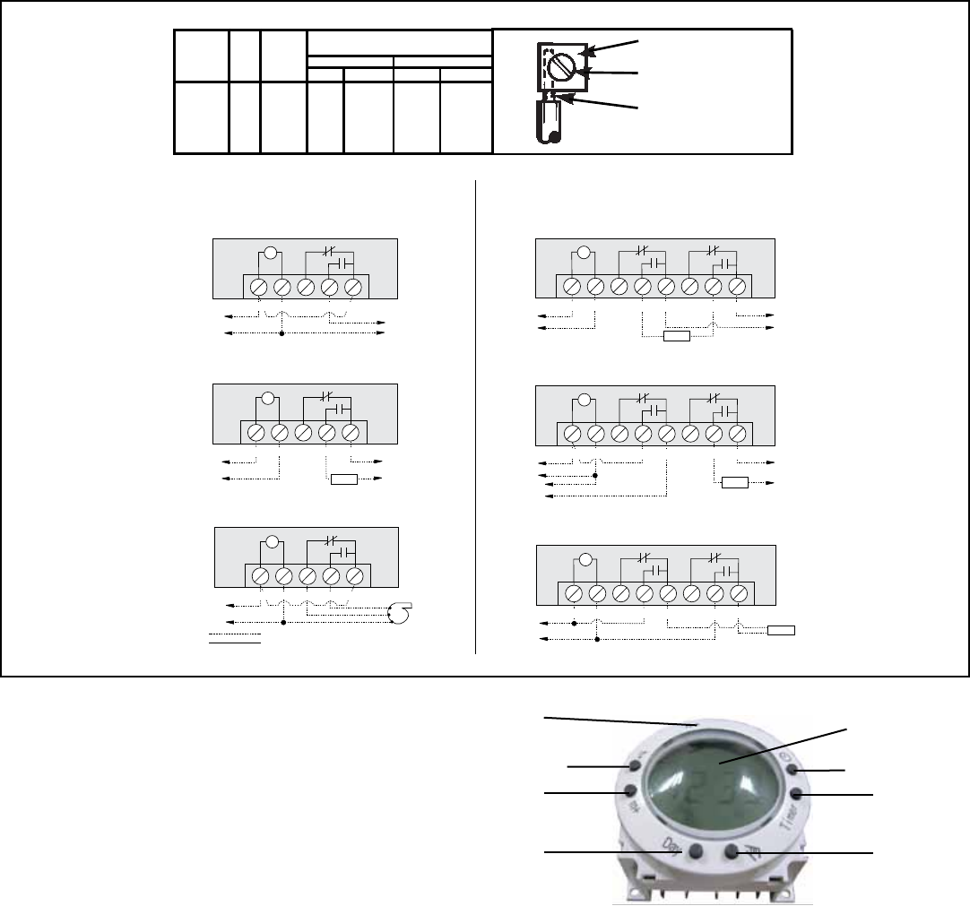
FIGURE 1
Override
(Manual ON/OFF Switched)
Timer
(9 Programs Setting)
Clock
(Current Time Setting)
LCD
(Function Figures)
R
(Reset)
H-
(Hours Setting)
M-
(Minutes Setting)
Day
(Days Setting)
OPERATING INSTRUCTIONS
BASIC SETTINGS:
Initial Set Up:
1. Push the “R” button before programming to clear out any settings. Once
the “R” button is pressed the screen will begin to flash. A paperclip may
be needed for this step.
(If the “R” button appears to stick down, use a toothpick to maneuver
it until it pops back up. The screen will flash if the button is popped up
successfully.)
2. Press the “Clock” button and the screen will stop flashing and be ready
for programming.
Setting the Current Time:
1. Press and Hold the “Clock” button during the entire setting.
2. Press the “H+” button to set the hours.
3. Press the “M+” button to set the minutes.
4. Press the “Day” button to set the day of the week.
5. Release the “Clock” button.
Programming ON/OFF Settings:
1. Press the “Timer” button once and the TIMER 1 ON - - : - - appears.
2. Press the “H+” and “M+” button to set the hours and minutes to the
desired time.
3. Press the “Day” button to select the day(s) the setting will be active. Refer
to the Multiple Weekday Group below to see the available settings.
4. Press the “Timer” button to store the setting and proceed to the next
setting TIMER 1 OFF - - : - -.
5. Repeat for all remaining setting options (9 Total ON/OFF settings). Once
completed press the “Clock” button to return to the main display.
Multiple Weekday Groups:
Apart from individual week days, pressing the “Day” button also selects
multiple day combinations such as:
- Monday thru Friday - Tuesday & Thursday & Saturday
- Saturday & Sunday - Monday thru Wednesday
- Monday thru Saturday - Thursday thru Saturday
- Monday & Wednesday & Friday - Monday thru Sunday
After setting a single day or a multi-day-combination the programmed timer
settings will be carried out on each of the week-days at the same time.
Programming Countdown Operation:
1. Press the “Timer” button to scroll through the 9 events settings to get to
the ON C setting.
2. Press the “Override” button to select whether the timer will turn ON or OFF
during teh countdown period.
3. Press the “H+” and “M+” buttons to set the hours and minutes of the
countdown.
4. Press the “Clock” button to store the setting and return to the current time
display. See the diagram below for more information.
PRESSURE PLATE
TERMINAL SCREW
MAKE SURE WIRE
INSULATION CLEARS
PRESSURE PLATE
MINIMUM
COPPER
WIRE SIZE
(AWG)
MAX.
LOAD
(AMP)
MIN.
INSUL-
ATION
TEMP(°C)
75°C INSULATION MAX. MOTOR
LOAD (HP)
SINGLE PHASE
3 PHASE
120 V. 240 V. 208 V.
240 V.
14
12
10
8
15
20
30
40
60
60
60
105
1/2
1
2
-
2
2 1/2
3
5
N/A
N/A