


3
DEH40206 Installation Instructions
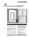
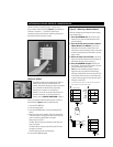
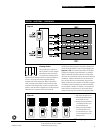
The 1-, 2- and 4-button dataline switches mount in standard
single-gang switch boxes. The 8-button unit mounts in a
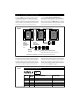
standard 2-gang box. The dataline is typically connected in a
“daisy-chain” from switch to switch, eliminating expensive
home runs. To assure proper operation, you must have a
good dataline which:
1. Provides 24 VAC power to each switch
2. Has a low resistance connection of the red and black wires
between all switches and the relay panel
3. Has no short of the red and/or black to ground
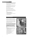
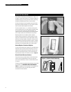
24 VAC Power
The power supply in the relay panel must be on. To test
for 24 VAC power at each switch, press the softwire tab after
you have connected the dataline but before mounting the
switch in the electrical box. The red LEDs for each button
should flash.
DATALINE SWITCH INSTALLATION AND TESTING
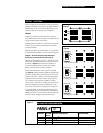
Low-Resistance Red/Black Data Path
After wiring the last switch on the local dataline, disconnect
the red and black wires from the Local Dataline terminals in
the relay panel and wire nut them together. Then measure the
resistance between the red and black terminals on the last
switch. It should be less than 3 ohms. If it is higher, work
backwards toward the relay panel, checking the resistance at
each switch to find the bad connection. When finished,
reconnect the Local Dataline at the panel.
Shorted Dataline
After the dataline resistance test checks out, you can easily
test for a shorted dataline by measuring the resistance from
red to white, then black to white anywhere on the dataline.
You should see an open circuit. If there is a short, start at the
last switch and work backwards as above to locate it.
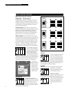
Self Installation and Unconfiguring
When the switch is first connected to a panel it is automati-
cally issued a network address—it is configured. If you are
moving a switch to another network you must first
unconfigure it to delete its network address. (A configured
switch could have the same address as a node on another
network.)
To unconfigure a switch, first make sure that the fourth DIP
switch is in the ON position. Leave the power line on but
disconnect the dataline. (Disconnecting the dataline prevents
the panel from configuring the switch again.) Hold down the
softwire tab for at least 10 seconds. At 10 seconds the locator
LED will turn off indicating that the switch is unconfigured.