


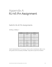

Appendix A: RJ-45 Pin Assignment
220 GE-DS-82 and 82-PoE Ethernet Managed Switch User Manual
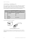
10/100Mbps, 10/100Base-TX
When connecting your 10/100Mbps Ethernet Switch to another switch, a bridge or a
hub, a straight or crossover cable is necessary. Each port of the Switch supports
auto-MDI/MDI-X detection. That means you can directly connect the Switch to any
Ethernet devices without making a crossover cable. The following table and diagram
show the standard RJ-45 receptacle/ connector and their pin assignments:
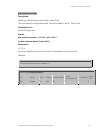
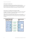
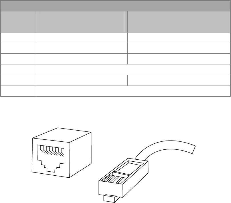
RJ-45 Connector pin assignment
Contact MDI
Media Dependant Interface
MDI-X
Media Dependant Interface-Cross
1 Tx + (transmit) Rx + (receive)
2 Tx - (transmit) Rx - (receive)
3 Rx + (receive) Tx + (transmit)
4, 5 Not used
6 Rx - (receive) Tx - (transmit)
7, 8 Not used
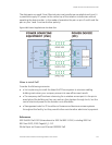
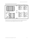
The standard cable, RJ-45 pin assignment
1
2
3
4
5
6
7
8
8
7
6
5
4
3
2
1
The standard RJ-45 receptacle/connector
There are 8 wires on a standard UTP/STP cable and each wire is color-coded. The
following shows the pin allocation and color of straight cable and crossover cable
connection: