


2. OPERATION LOGIC
GEK-106168E DBF Breaker Failure Protection 9
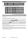
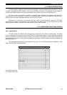
Group Status Comment
4.0 - 4.15
5.0 -5.15
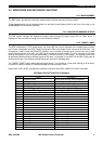
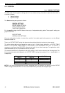
The DBF units are supplied with the following target LED’s default configuration:
LED
Nº
LEFT COLUMN LED
Nº
RIGHT COLUMN
1 TRIP STAGE 1 9 LOW SET PICKUP
2 TRIPSTAGE2 10 50BFPOLEAINIT
3 PHASEATRIP 11 50BFPOLEBINIT
4 PHASEBTRIP 12 50BFPOLECINIT
5 PHASE C TRIP 13 INT. ARC A POLE
6 3PTRIPNOI 14 INT.ARCBPOLE
7 INT. ARC TRIP 15 INT. ARC C POLE
8 HIGH SET PICKUP 16 REMOTE COMMUNICATIONS
2.2.4 CIRCUIT BREAKER BREAKING CAPACITY MONITORING
To supervise the breaker health, the DBF system calculates and stores, for each operation, the accumulated
values of the square of the current multiplied by the opening time of the breaker (I
2
t) on each phase. I
2
tis
expressed in kA
2
sec.
The value I
2
t is accumulated and stored independently for each phase. These values can be accessed either by
the local HMI or by the GE-LOCAL communications software.
The function has an
Integration Time Selector
setting (kI
2
tOPMODE)whichcanbeusedtoassignafixed
opening time (given by another setting (kI
2
tINTTIME)). Otherwise the unit measures the time between the
tripping signal of the main feeder protection and the change of the status contacts of the circuit breaker (52/b).
The total
Breaking Current Limit
(kI
2
t LIMIT) setting fixes the maximum life breaking capability (it is recommended
to set this to the limit supplied by the manufacturer). When this threshold is reached in any phase, the system
may be configured to close an output, if the appropriate internal signal (52 A Maintenance Alarm, 52 B
Maintenance Alarm, 52 C Maintenance Alarm) is assigned to an output. In addition, the system also has a
counter for the tripping operations.
The purpose of these functions is to provide accurate data to perform the circuit breaker maintenance, based on
the actual breaking time and current values. Once this maintenance operation has been done, the values for both
the I
2
t and number of opening operations, can be reset.
In order to be able to take into account the history of the breaker, in the case where the breakers were already in
use before the installation of the relay, the system allows to set an initial value for the I
2
t and the number of the
previous breaking operations. Similarly, these values can be adjusted to a given value in order to take into account
operations carried out during protection testing.