


5. HARDWARE DESCRIPTION
GEK-106168E DBF Breaker Failure Protection 25
5.
5. 5.
5. HARDWARE DESCRIPTION
HARDWARE DESCRIPTIONHARDWARE DESCRIPTION
HARDWARE DESCRIPTION
CAUTION
The DBF contains electronic components that can be damaged by electrostatic discharge if currents flow
through some terminals of the internal components. The main source of electrostatic discharge currents
is the human body, especially in conditions of low humidity, carpeted floors and isolated footwear. Under
these conditions it is important to have special care when removing and handling the modules or some of
their internal components. Personnel handling the relay should check that their body is free from
electrostatic charge, either by touching a surface at ground potential or by using an electrostatic
wristband connected to earth.
5.1. PHYSICAL DESCRIPTION
5.1.1. CASE
The DBF case is made of stainless steel and consists of the main body and a covering lid. The main body of the
case contains the blocks of terminals necessary to carry out the external connections and guides to support the
trays that contain the internal parts of the relay. The trays can be pulled out in order to make easy the
maintenance and servicing of the relay.
5.1.2. ELECTRICAL CONNECTIONS
All the electrical connections for current channels, digital input and output relays are made using the terminal
blocks fixed to the rear part of the case. The connections required for communications are made using three DB-9
serial connectors, one on the front and two on the rear when using communication option RS-232. One of these
connectors is replaced by the corresponding fiber-optic connector in models including this option.
5.1.3. INTERNAL CONSTRUCTION
Internally the DBF unit is divided into 2 trays and a case. The case with the blocks of terminals is described above.
The lower tray carries the magnetic module and a printed circuit board which contains the power supply, the digital
inputs and also the trip outputs and auxiliary outputs on the basic version (model without expansion board).
The upper tray carries the board with the protection system CPU and the communications. This tray can also carry
as an option the input and output expansion board.
The front panel consists of a covered keyboard and a board which carries the alphanumeric display, the LEDs and
the Reset button. The model number (see list of models in Chapter 4) and the technical characteristics of the unit
are situated on the front panel of the relay.
The 16 indicator LEDs can be identified using labels which can be placed beside them, inside available plastic
holders.
A frontal bus is responsible for the connections between the lower and upper trays described above. Both trays
can be pulled out. To do so you first have to release the front panel which is fixed to the case with two screws and
pull it out, removing the flat cable which connects it to the CPU. It is then possible to remove the frontal bus.
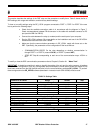
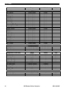
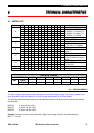
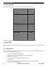
The blocks of terminals situated on the rear of the case are identified with the letters A, B, C and D, and optionally
E and F, as shown in figure 9. In addition, each terminal is identified with a number.