


1
3Chapter 1 Introduction
LEDs
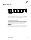
The Remote I/O Scanner has three LEDs that show through the transparent portion at
the top of the door.
lights to indicate that the module has passed its powerup diagnostic
tests. If this LED flashes, it indicates a problem, as shown in the table
below. If this LED is off, there is a fatal error, which causes the Remote
I/O Scanner to go to stop/faulted mode.
lights when the Remote I/O Scanner is receiving the expected output
data from the CPU. If this LED flashes, it indicates either I/O data is
forced, or a Device Number conflict.
if the Remote I/O Scanner is installed on a dual (redundant) bus, this
LED lights if Bus B of the dual bus pair is the currently–active bus.
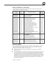
The following table summarizes the LED indications.
Module OK I/O Enabled Meaning
On On Normal operation
Blinking On Fault detected
On Blinking I/O data forced
Alternate blinking Alternate blinking Fault detected, and I/O data forced
Synchronous blinking Synchronous blinking Device Number conflict
On Off Outputs not being updated from CPU
Off Off No power or fatal error
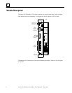
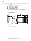
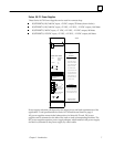
Connectors
The front of the module has three connectors:
9–pin male D Connector: the upper connector. Used for attaching a Genius
Hand–held Monitor.
15–pin female D Connector: the center connector. This connector is an RS–422
compatible RS–485 serial port. It can be used for communicating with a
programmer equipped with the serial version of Logicmaster 90–70, or for
connection to a multidrop communications network.
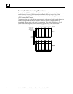
The connector at the bottom of the module attaches the Genius bus terminal strip.
Because the terminal strip is removable, it is possible to service or replace the
Remote I/O Scanner while the rest of the system is operating, without disrupting
bus communications.
Module OK
I/O Enabled
Bus B Active