


7
107Chapter 7 Remote Drop I/O Data
Monitoring/Controlling I/O Data:
Logicmaster 90–70
Logicmaster 90–70 can be used to monitor I/O in the remote drop, either from the
PLC I/O Tables or from the Remote I/O Scanner’s internal I/O tables.
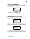
Reference Tables Display from the PLC
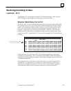
When the system is in operation and the remote drop is communicating with the PLC
via a Genius bus, the I/O in the remote drop can be monitored as part of the complete
system. The Logicmaster reference tables displays will include those portions of the
PLC’s %I, %Q, %AI, and %AQ memory being used by a Remote I/O Scanner. For
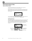
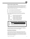
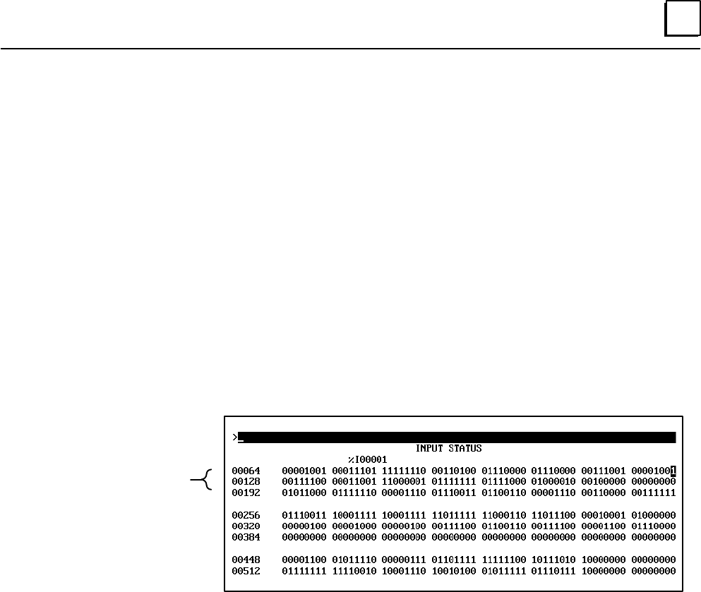
example, a remote drop uses discrete inputs %I00001 – %I00120. In the reference
tables for the PLC, these inputs are displayed along with other system inputs. When
attached to the PLC, Logicmaster 90–70 can override or toggle the I/O data and cause
a change.
%I References used by
Remote I/O Scanner
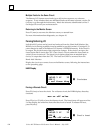
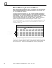
If the remote drop is on–line to the PLC, I/O cannot be toggled by a programmer
attached to the remote drop. This is because the altered data would be immediately
overwritten by the real input and output values being exchanged between the Remote
I/O Scanner and the PLC.
If the system is not yet in operation or the remote drop is not transferring I/O data
with the PLC over the Genius bus, monitoring must be done at the remote drop.
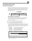
Either serial or parallel Logicmaster 90–70 can be used. In this situation, toggling
output data is possible and can be useful in checking out circuit connections.