


D
Series 90–70 Remote I/O Scanner User’s Manual – July 1992142
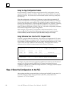
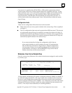
Remote Drop Configuration Summary
Configuring a remote drop with Logicmaster 90–70 is similar to configuring a rack
with a CPU and I/O modules. The configuration steps are:
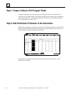
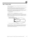
1. Select or create the folder for the remote drop configuration.
For a Series 90–70 PLC host, this should be located in the central PLC’s drawer,
with the name of the remote drop _DROPxxx, where xxx is the remote drop ID
(016–254).
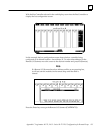
2. Configure the Remote I/O Scanner module in rack 0, slot 1. For a new folder, this
involves replacing the default CPU (which appears in rack 0, slot 1) with a Remote
I/O Scanner.
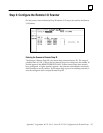
Configuration includes selecting the Remote Drop ID (the remote drop’s SNP ID)
to be used for serial multidrop communications. Configuration also includes
selection of the remote I/O map outline (corresponding exactly to that defined in
the PLC folder).
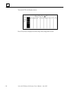
3. Configure the I/O modules into the rack (normally within the confines of the
remote I/O map). If it is possible that a remote drop may be added to in the future,
leave some vacant I/O references immediately above those used for the remote
drop. Otherwise, adding modules later may necessitate a shuffle or a complete
reassignment of I/O references.
4. Store the completed configuration to the remote drop. This can be done at any
time.
A. Connect the programmer to the remote drop, or select the remote drop for
serial communications. Connection is made to the serial port on the Remote
I/O Scanner for the serial version of Logicmaster 90–70. Connection is made
to the communications port on the Bus Transmitter Module in the remote drop
for the parallel version of Logicmaster 90–70.
B. Store the configuration to the Remote I/O Scanner using the Utility functions.
If you need more information to complete the configuration steps, please refer to the
Logicmaster 90–70 Software User’s Manual.