


1
Series 90–70 Remote I/O Scanner User’s Manual – July 199214
Redundancy
The Remote I/O Scanner can be used with CPU redundancy, bus redundancy, or both.
The suitability of redundancy features for any system depends on the requirements of
the application. For Series 90–70 PLC CPUs that are release 3 and earlier, some types
of redundancy are not supported.
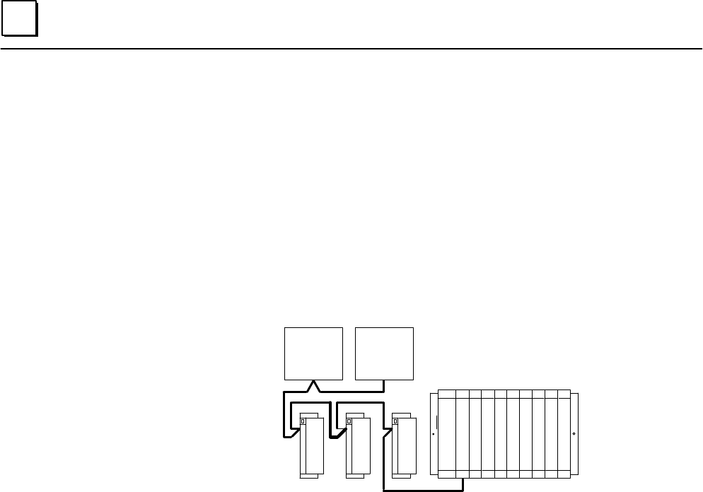
CPU Redundancy
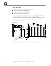
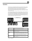
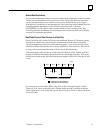
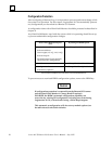
Genius devices are considered to be controlled by the Bus Controller that sends them
outputs. In CPU redundancy, two Bus Controllers on the same bus can send control
outputs at the same time. The Bus Controllers must use Device Numbers 30 and 31.
BUS
CONTROLLER
(DEVICE 31)
BUS
CONTROLLER
(DEVICE 30)
REMOTE DROP
A
S
C
N
N
E
R
a44876
P
S
Both Bus Controllers automatically receive inputs and fault reports from all devices on
the bus that have been configured as being in “CPU Redundancy“ mode.
How the two sets of outputs are handled by devices that receive them depends on
whether the devices are set up for Hot Standby or Duplex redundancy. Both are
explained below. If the remote drop contains any analog modules, the only form of CPU
redundancy permitted is Hot Standby.
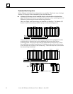
Hot Standby CPU Redundancy
A device configured to be in Hot Standby redundancy mode is normally controlled by
the Bus Controller assigned to Device Number 31. If no outputs are available from that
Bus Controller for a period of three bus scans, the device accepts outputs from the Bus
Controller assigned to Device Number 30. If outputs are not available from either Bus
Controller, outputs go to their configured defaults or hold their last state. In Hot
Standby redundancy, Device Number 31 always has priority, so that when that Bus
Controller is on–line, it has control of the outputs.
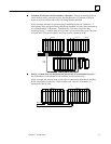
Duplex CPU Redundancy
A device configured to be in Duplex redundancy mode compares the outputs it
receives from the two bus controllers, to determine whether they match. If
corresponding outputs are the same, the device sets the output to that state. If
corresponding outputs are not the same, the device sets the output to its configured
ON or OFF Duplex Default State. If either Bus Controller stops sending outputs to a
device, its outputs are directly controlled by the remaining device. Only discrete devices
can operate in Duplex redundancy mode; do not use Duplex mode if the analog drop contains
any analog modules.