


1
15Chapter 1 Introduction
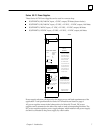
Genius Bus Redundancy
In Genius bus redundancy, there are two bus cables each connected to a Bus Controller.
The device communicates on only one bus at a time. Before the alternate bus can be
use for communications, a bus switchover must occur and the device must “log in“
with the Bus Controller(s) on the alternate bus. Bus switching can be handled by a Bus
Switching Module attached to a Genius block, or by a Remote I/O Scanner
(IC697BEM733 rev. B or later) which contains a built–in bus switching relay. Bus
Switching Modules and Remote I/O Scanners are the only devices that can be directly
connected to redundant bus cables.
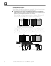
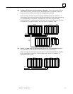
Bus Stubs Connect Other Devices to a Dual Bus
Other Genius devices, such as I/O blocks and additional Remote I/O Scanners, can be
interfaced to a dual bus by short lengths of unterminated cable called a bus stubs.
Typical arrangements are shown on the following pages. Up to seven devices can be
installed on a bus stub (plus the device that is connected to the dual bus). Each device
on a bus stub counts toward the total of 32 devices on the Genius bus.
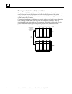
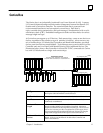
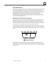
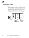
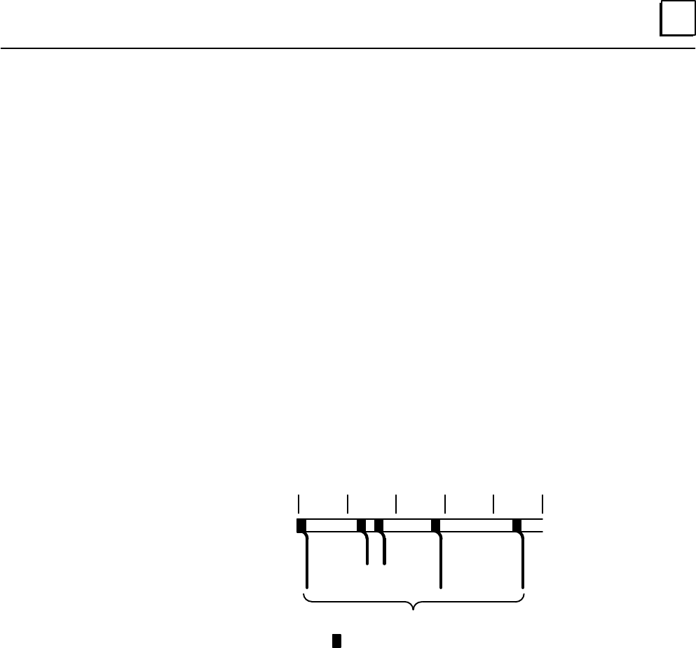
The total length of all bus stubs on a bus should be 100 feet or less. Within each 20%
section of the actual bus length, the total maximum stub length is 20 feet. This can be
divided into shorter stubs, provided that the total length in each 20% of the bus is 20 ft.
or less.
a44976
20% 20% 20% 20% 20%
10’ 10’
20’
20’
COMBINED = 100 FEET MAXIMUM
= REMOTE I/O SCANNER OR
BUS SWITCHING MODULE
20’
For example, for a trunk cable 3000 ft. long, 20% of the trunk cable length is 600 ft.
Therefore, 20 ft. of bus stub cable can be located within any 600 ft. section of the bus.
There might be two 10 ft. stubs with up to 8 devices each, or four 5 ft. stubs, with fewer
devices on each.