


2
Series 90–70 Remote I/O Scanner User’s Manual – July 199224
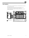
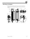
Rack Grounding
Complete safety and reference ground connections from the GND terminal on the
rack to earth ground using minimum AWG #12 wire and a ring terminal. Use of a
nut and star washer for each wire on the GND lug is recommended to ensure
adequate grounding.
Warning
If the ground lug on the rack is not connected, the rack is not
grounded. The rack must be grounded to minimize electrical shock
hazard which may result in severe personal injury or may be fatal.
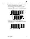
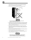
All racks that are grouped together MUST have a common ground connection.
This is especially important for racks which are not mounted in the same cabinet.
Connect the rack frame directly to the control panel or rack on which it is
mounted. Attach a ground strap from one of the ground lugs on either side of the
rack to the control panel or cabinet following applicable electrical safety codes.
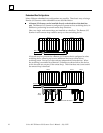
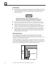
Use the bottom rail of the rack for module shield grounding. Some modules have
a ground clip that contacts the conductive bottom rail when the module is fully
inserted. Shield connections in the user connector are routed to this ground clip
through conductors on the module.
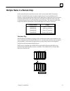
Rack Number Selection
Before installing the power supply or power supply adapter in the rack, set the
rack–number jumpers. Each rack in a remote drop must have a rack number
between 0 and 7. Rack number 0 must always be present; in the remote drop, it is the
rack that contains the Remote I/O Scanner.
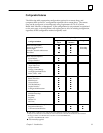
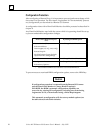
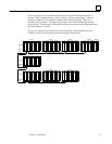
To select a rack number, move jumpers X1, X2, and X4 so that the sum of the numbers
in the 1 (right) position equals the desired rack number. Jumper X8 must always be in the
0 (left) position. The jumper plug connects the middle post under the 1 or 0 column as
shown in the following example, which shows jumper positions for rack 2.
a42823
01
8
4
2
1
RACK NUMBER =2