


2
Series 90–70 Remote I/O Scanner User’s Manual – July 199228
Module Installation and Removal
Warning
Always be careful working near the power supply and the wiring to
I/O boards in the rack. Be sure a protective faceplate cover is
installed on each board. Voltages present on I/O wiring and power
supply could cause severe or fatal injury to personnel.
Caution
Do not insert or remove a module when power is applied to the rack.
This could cause the system to stop. Use care when inserting or
removing a module so that the printed circuit board or its
components are not damaged.
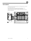
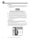
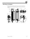
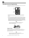
Installing a Module
Install each module with its component side to the right. The LEDs will be at the top
front.
1. Be sure the rack in which the module is to be inserted is powered–down.
2. Grasp the module firmly with your hand and insert it into the card guide.
3. Align the module’s printed circuit board with the connector on the rack backplane
and slide it towards the connector until it has started to seat.
4. Place one thumb on the left side of the top plastic flange and the other thumb on
the left side of the bottom plastic flange. Push the board into the connector until
the top and bottom latches click onto the rack rails.
5. Visually inspect the board to be sure it has seated properly.
6. If the rack is in a high–vibration area, use screws to secure the module in the rack.
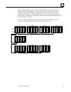
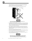
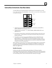
Removing a Module
1. Be sure the rack is powered–down.
2. Grasp the module firmly at the top and bottom of the board cover with your
thumbs on the front of the cover and your fingers on the plastic clips on the back
of the cover.
3. Squeeze the rack clips on the back of the cover with your fingers to disengage the
clip from the rack rail and pull the board firmly to remove it from the backplane
connector.
4. Slide the printed circuit board along the card guide and remove it from the rack.