


2
31Chapter 2 Installation
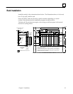
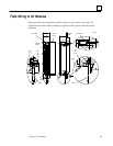
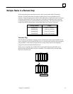
Multiple Racks in a Remote Drop
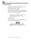
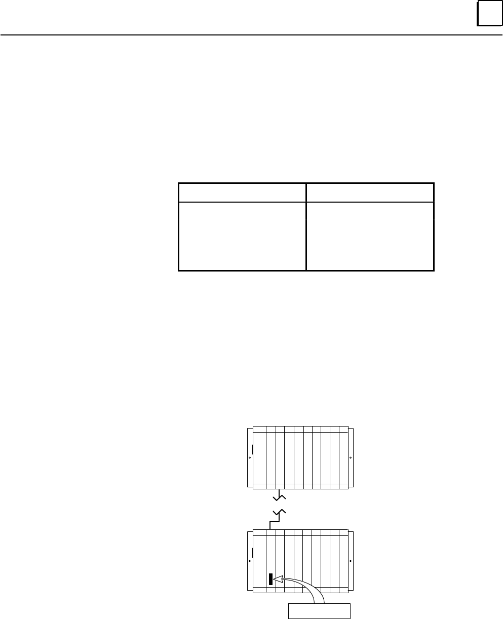
If the remote drop has more than one rack, rack 0 must contain a Bus Transmitter
Module. The Bus Transmitter should be installed in slot 2, next to the Remote I/O
Scanner. Using the appropriate cable (see the table below), attach the bottom connector
of the Bus Transmitter to the top connector of a Bus Receiver Module in the next rack.
Continue this process to connect all of the racks in the drop. The maximum total cable
length from the Bus Transmitter to the last Bus Receiver is 50 feet (15 meters).
Catalog Number Length
IC600WD005 5 feet (1.5 meters)
IC600WD010 10 feet (3.0 meters)
IC600WD025 25 feet (7.5 meters)
IC600WD050 50 feet (15.0 meters)
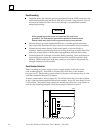
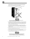
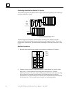
Terminator Plug
Each Bus Receiver Module is shipped with a termination resistor pack installed in the
lower connector. Only the last Bus Receiver in a remote drop may have the terminator
plug installed. If the remote drop has three or more racks, remove the terminator
plugs from the intermediate Bus Receivers.
When power is applied, the middle LED on the last Bus Receiver should be on to
indicate that the termination resistor is installed. The middle LED on all other Bus
Receivers should be off.
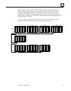
LAST RACK
a44971
P
S
M
B
T
A
S
C
N
N
E
R
7 EXPANSION RACKS (MAXIMUM)
RACK 0
B
R
M
P
S
I/O TERMINATOR PLUG
(IC697ACC702)